DIY Tube Amps Builds 🎸
Tubes and FETs, Guitars and Rock'n'Roll
There are many many ways to build an amplifier, depending on money and time available, choosing the most expensive components, creating (or again, buy) a custom metal chassis (or have a friend that can make many as you want) with the objective to obtain a better build for the same price.
Building tube amps is very rewarding, and can keep you busy with its fair amount of metalwork and various power tools, like folding machines, press, lathe, milling machines and uncountable hand tools. Finishing the build with spray paint, adding lettering, logos, design elements one can go on forever. Custom shop!
Building Tube Amps Builds builds your knowledge and skills
- getting an electric shock
- getting physically hurt
- the build time can be humongous and inversely proportional to the playing time
- the build time might keep extending due to improvements and continuous integration
- there can be failures
Main advantages are:
- you will learn how to deal with high voltages
- you will learn how physical phenomena really works and how all those math formulas you saw at high school become alive
- you will learn how different materials can be glued and joined
- you will learn lots of tricks
At the end of the day you can proudly showcase your rig and let somebody else play on it, until you clean up your workplace and get some sleep!
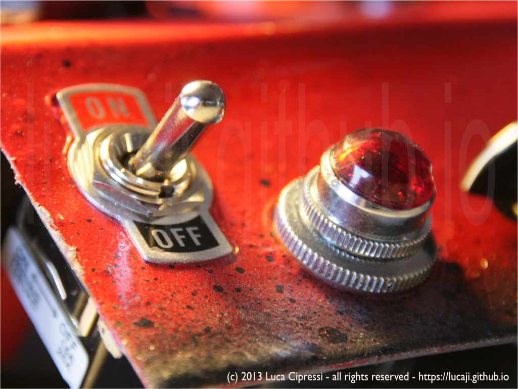
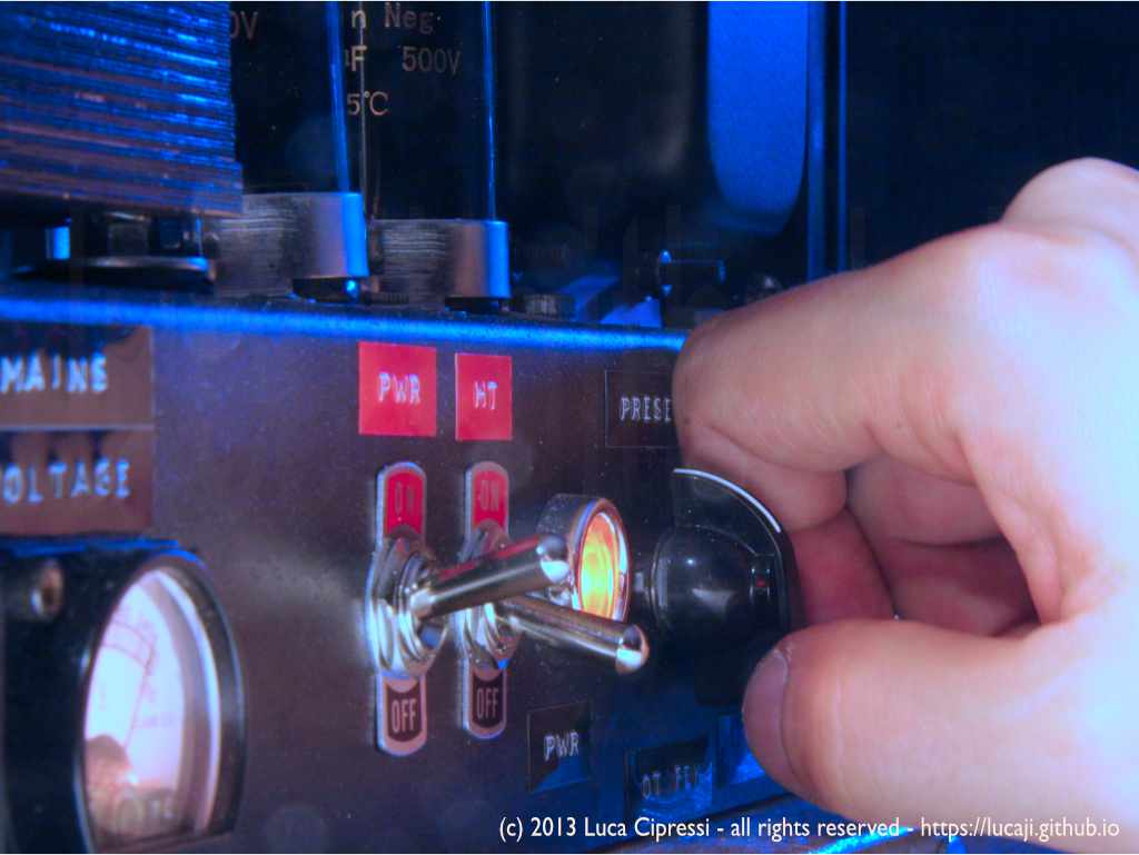
The greatest thrill is always there when turning the power on switch the very first time for each build. Everytime.
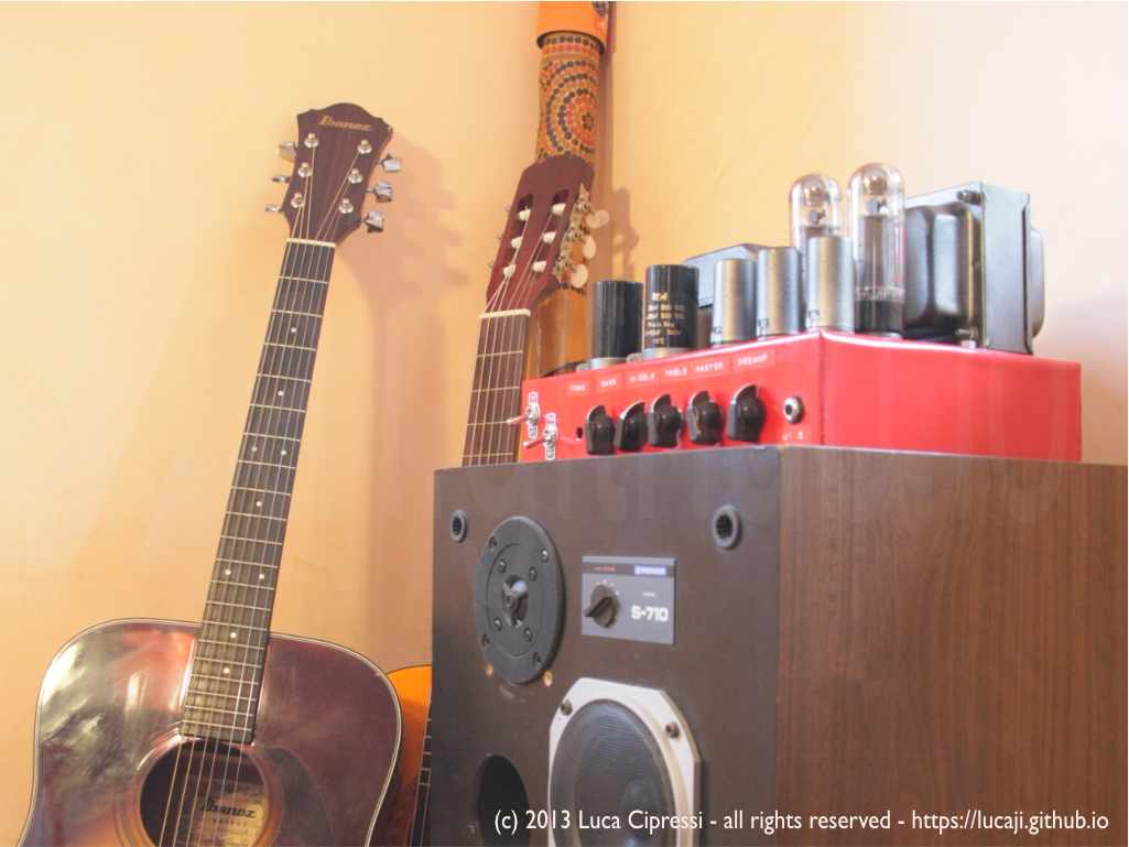
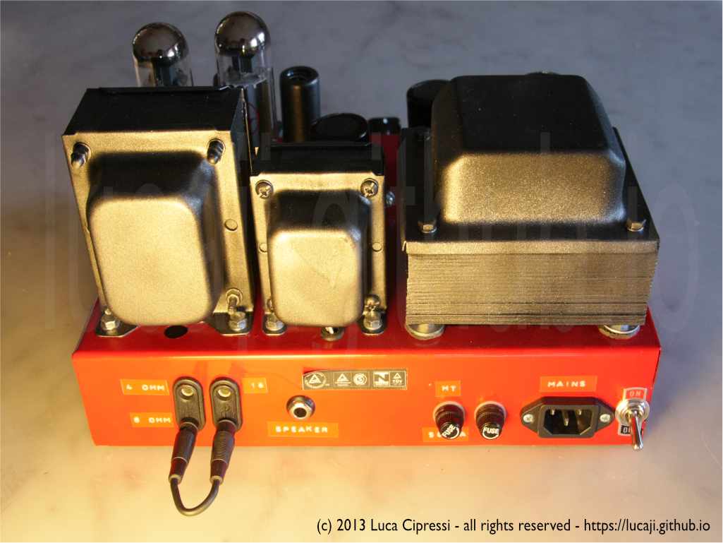
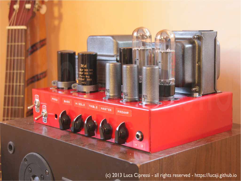
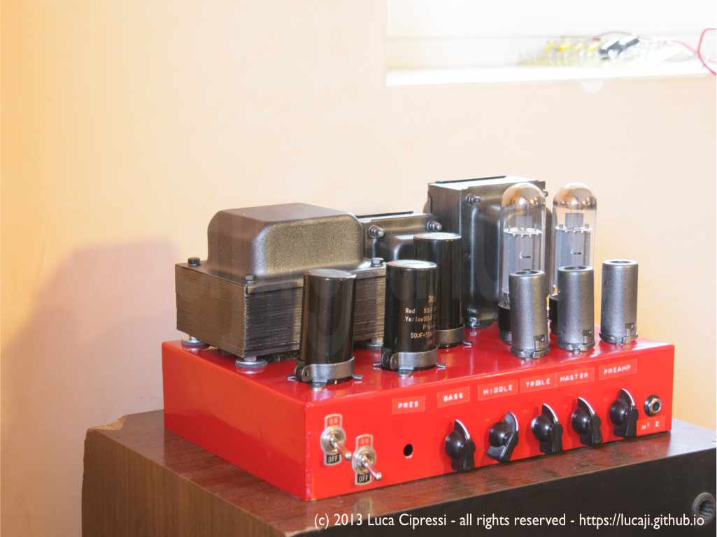
MARSHALL-ATTACKS!
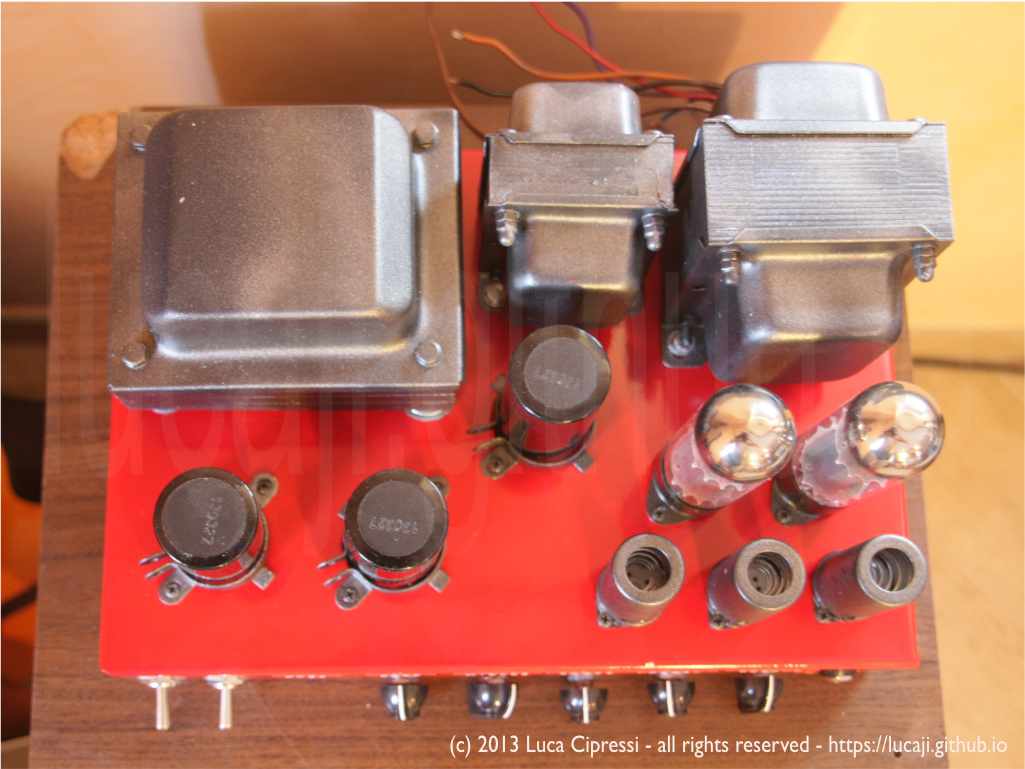
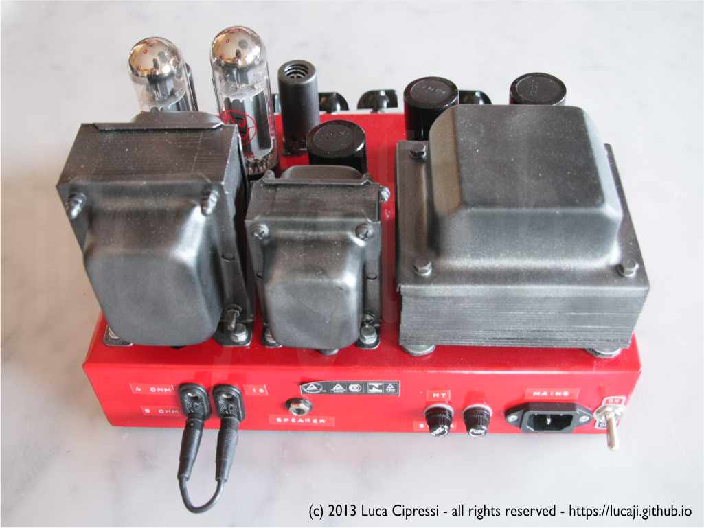
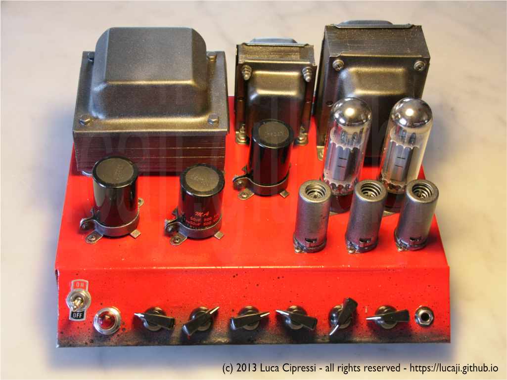
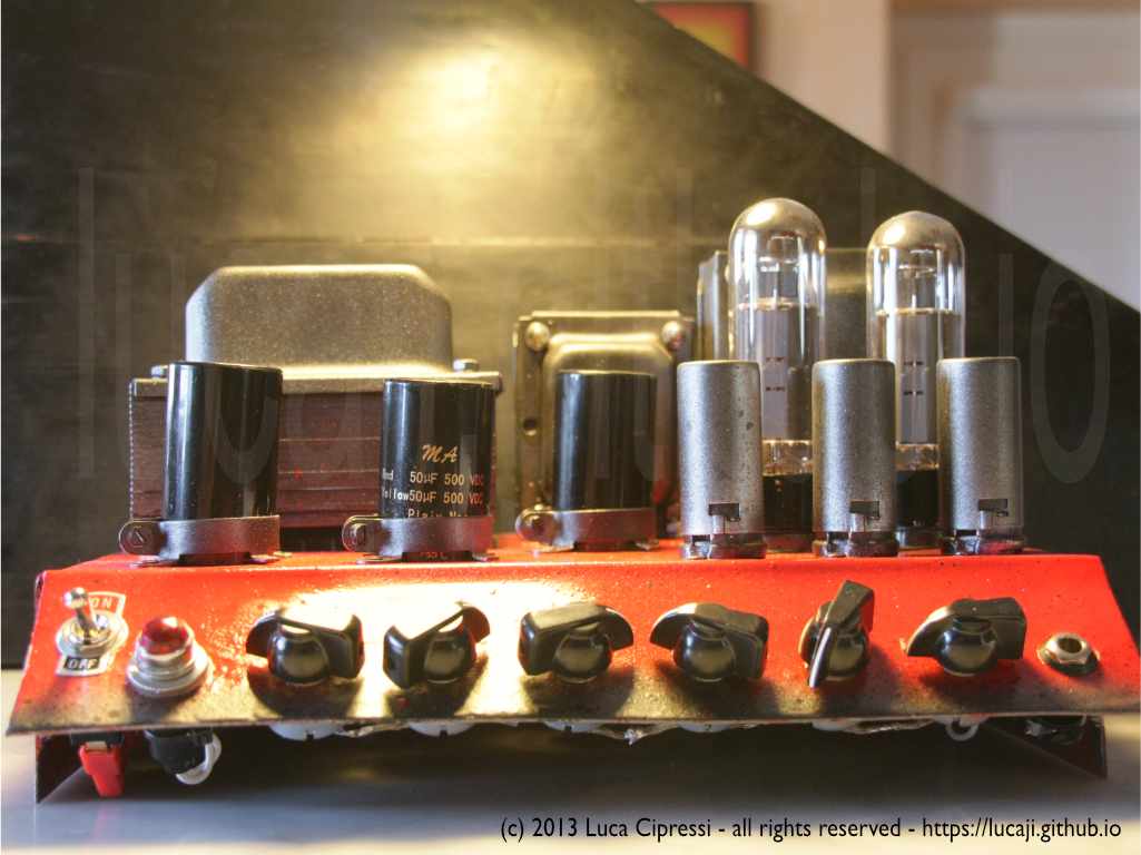
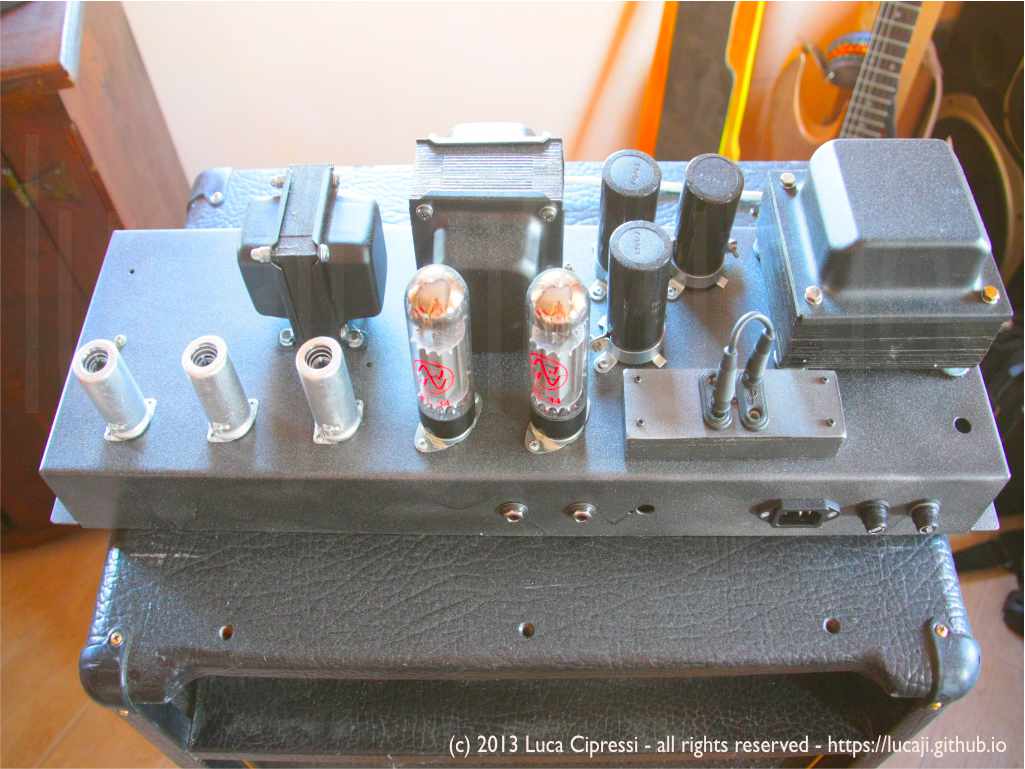
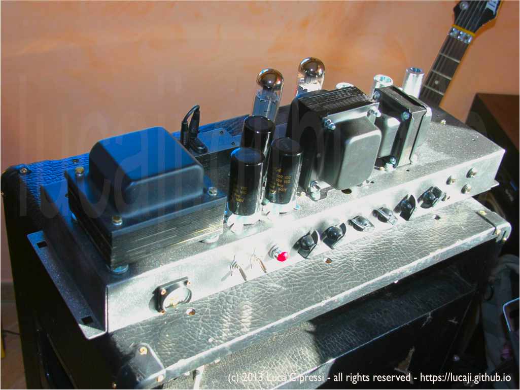
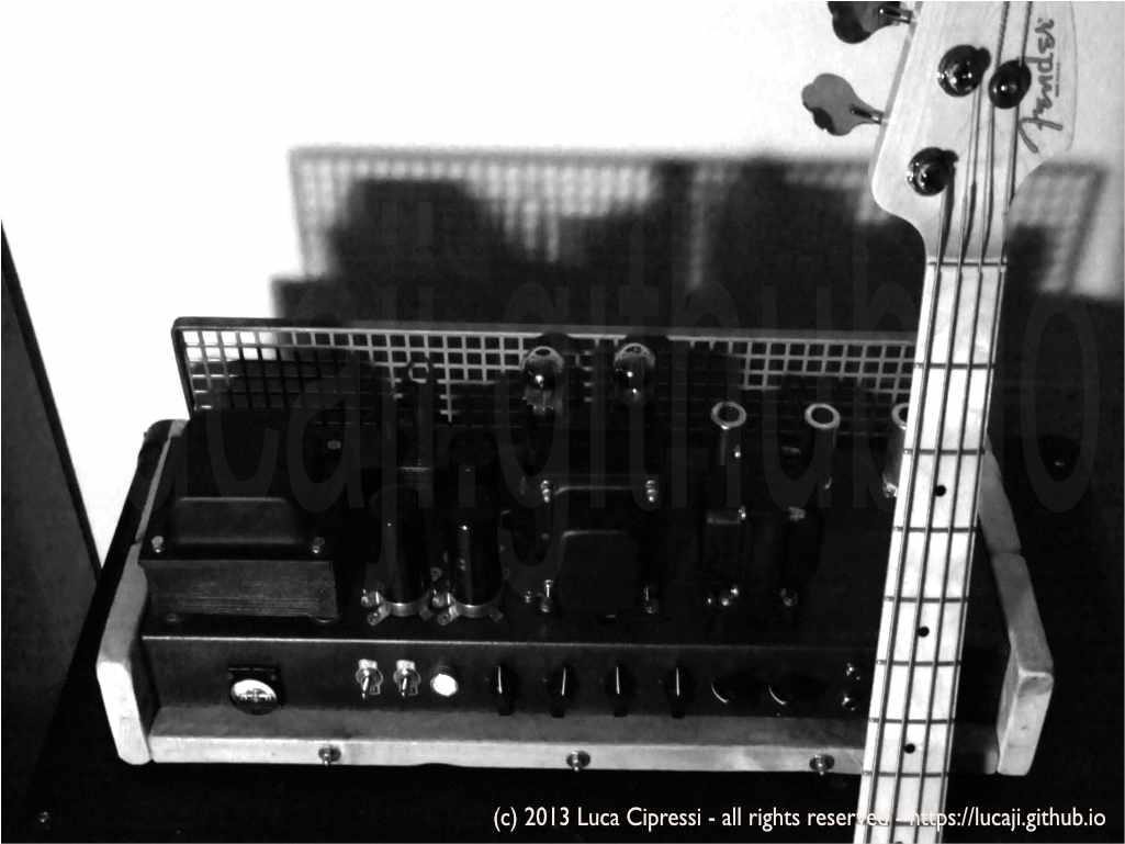
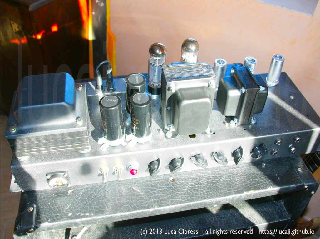
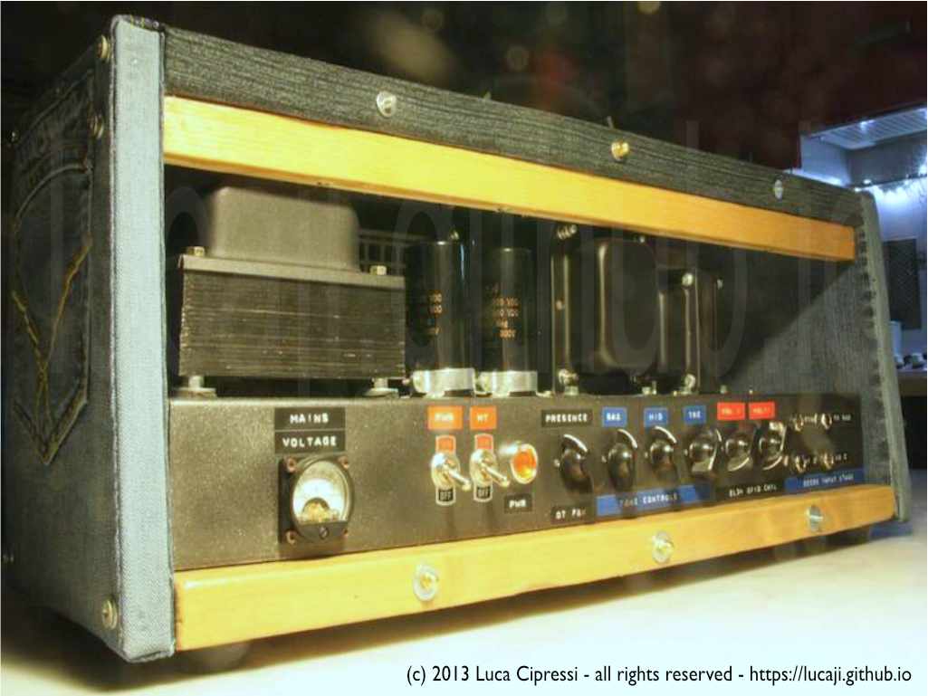
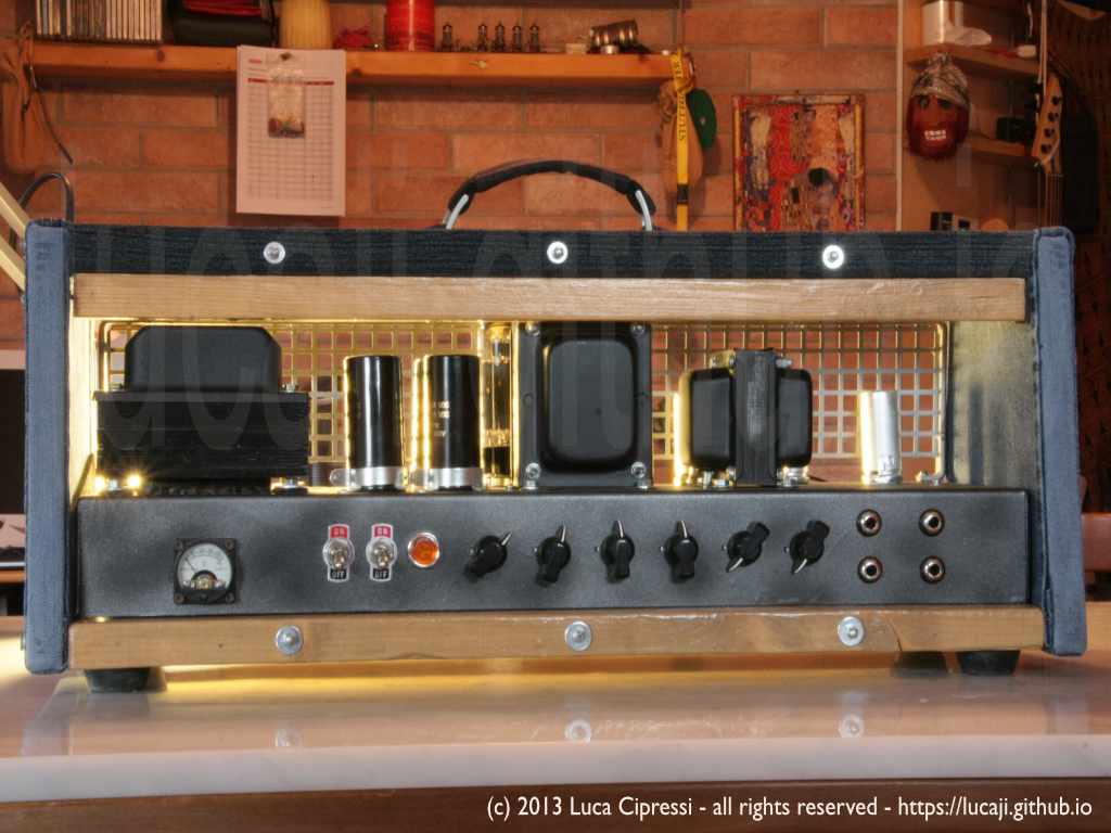
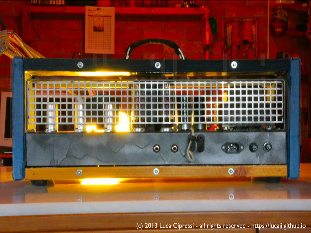
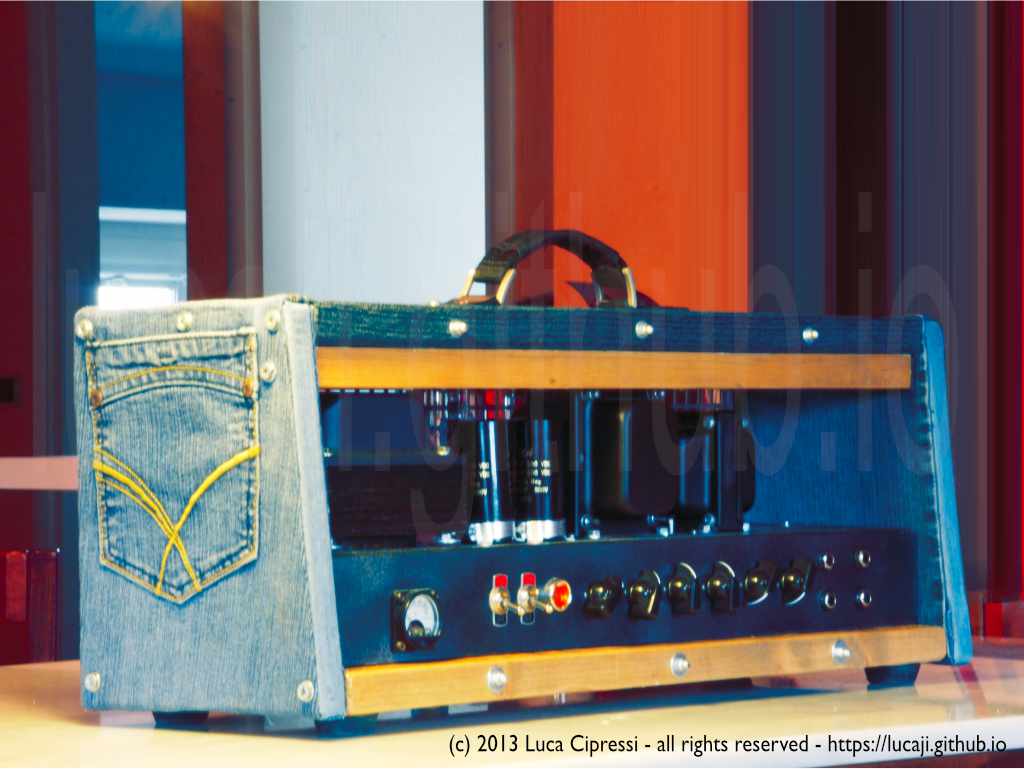
The following gallery displays some different builds of the Marshall JCM800 Master Volume Lead specifically the 2204 model.
Specification 2204 (measured at 1kHz, controls set to maximum, top input channel)
- low sensitivity input 17 mVrms (-33dBu)
- high sensitivity input 150 pVrms (-74dBu)
- 50Wrms output power THD 3%
- 2x EL34 power tubes
- class B push-pull configuration
- EQ Treble 10kHz, EQ Mid 500Hz, EQ Bass 50Hz
- 4, 8, 16 ohm output impedance (selectable)
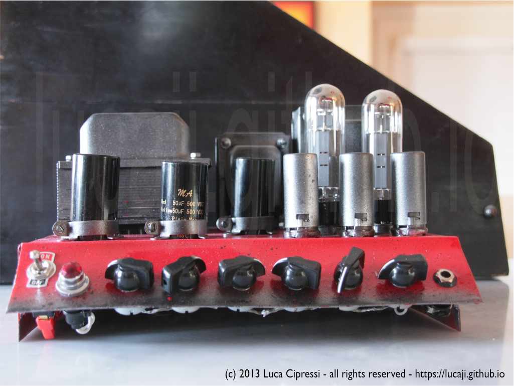
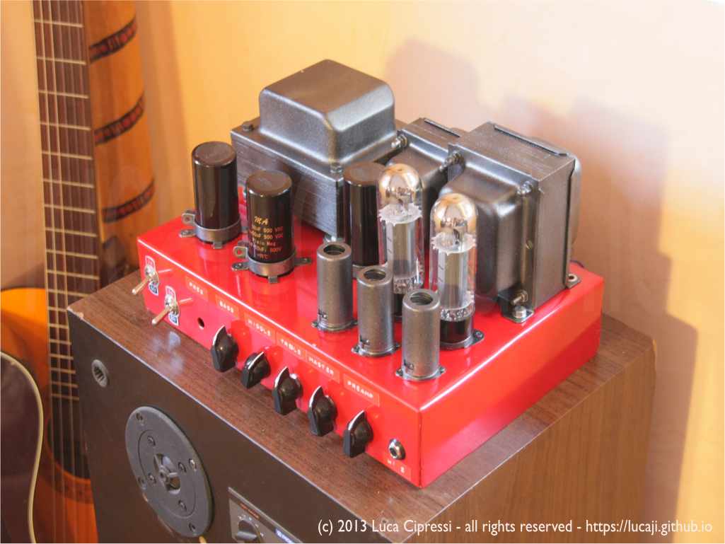
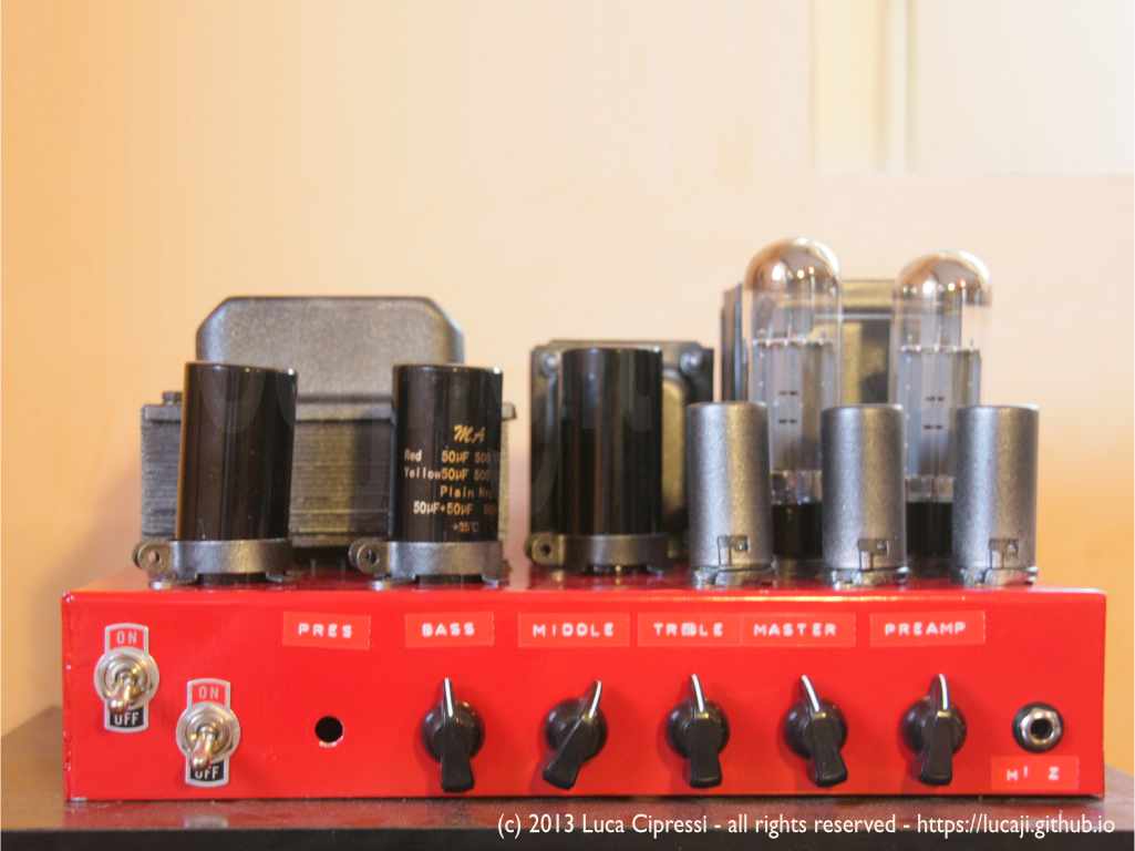
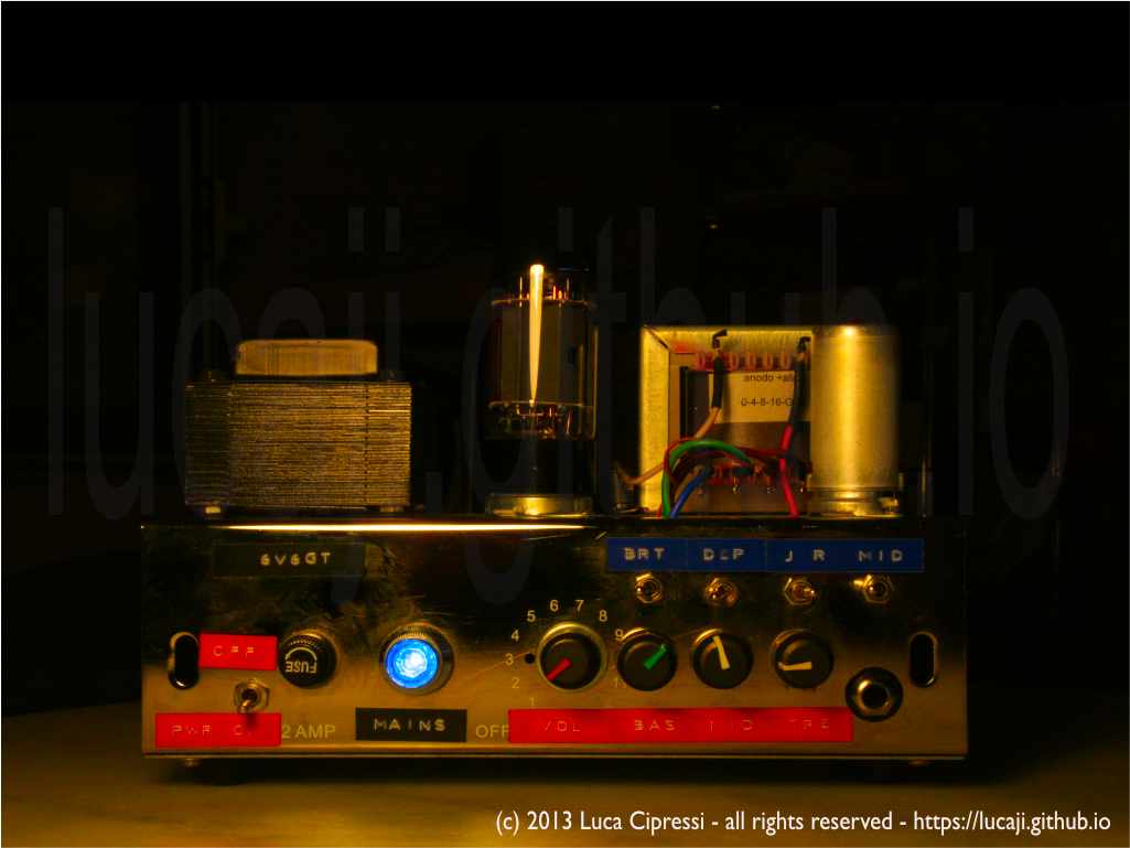
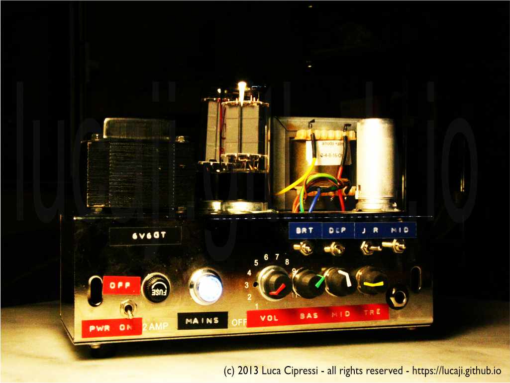
FENDER Champ-Amp Table-Top
This build is my favourite and I plan to spend more time on it, as it is an ideal project to learn how to build tube-amps and it gives lots back in term of satisfaction when playing with it.
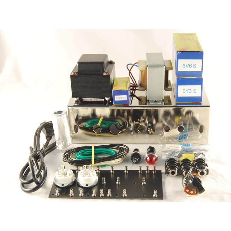
Inspiration
The inspiration for this build came from the VOX Night Train series which caught my eye especially for the form-factor and beautiful metallic case with grill.
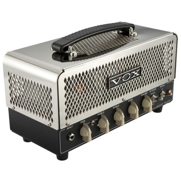
VOX Night Train - NT15H Head
Even though VOX used to make the LIL’NIGHT TRAIN version, which has (only) 2W of pure tube tone into 16 ohm speaker impedance, it uses exclusively 12AX7 dual-triodes for pre-amp stages and a 12AU7 at the final stage, so it uses like its bigger brother, a push-pull configuration for the output.
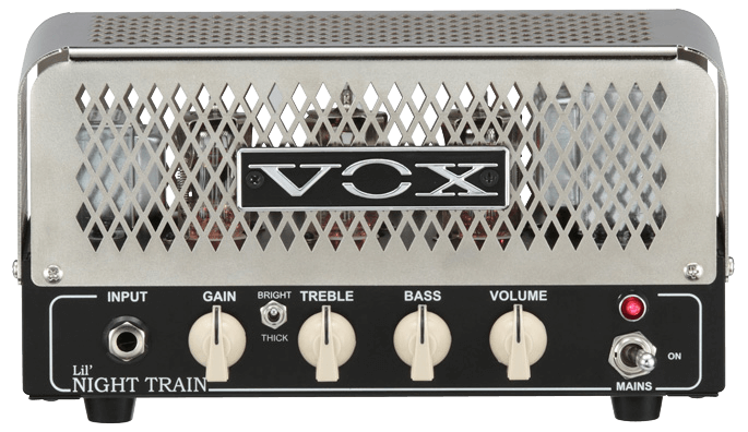
VOX LIL'Night Train
VOX Front
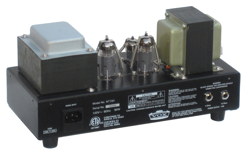
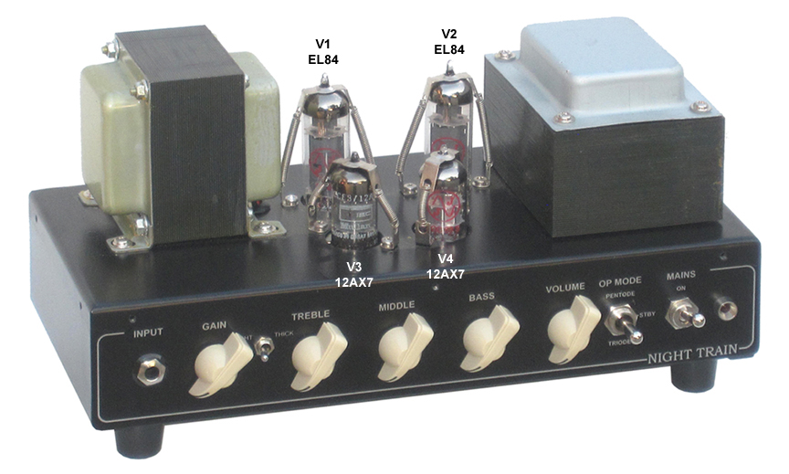
VOX Rear
Being particularly fond of the class A configuration of the Fender Champ-Amp, I took its original schematic one step further adding a passive tone-control circuit.
Audio Precision Measurement
The DUT has been connected and tested using an APx585 Audio Analyzer. The generator output was feeding the amp input and its 8R output is connected to a pure resistive load of the same impedance which feeds the analyzer balanced input directly. The DUT is powered via an AC generator set to 230VAC.
Frequency Response Gain
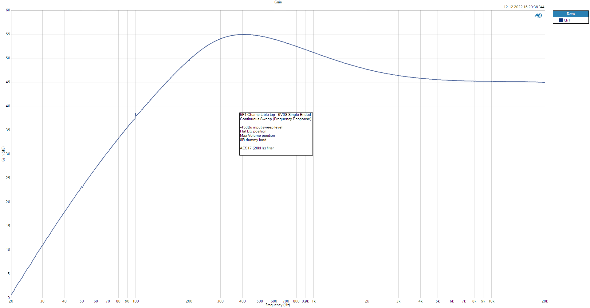
Frequency Response Gain
Stepped Frequency Sweep
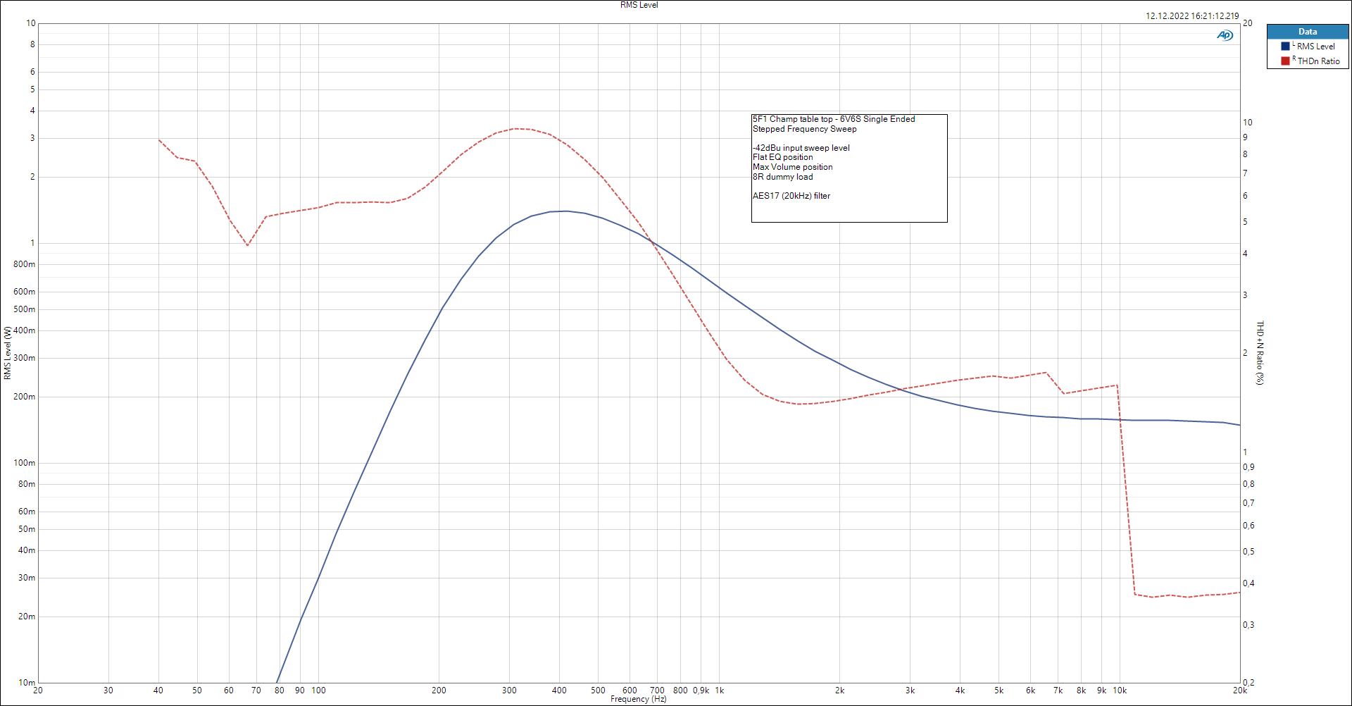
Stepped Frequency Sweep RMS Level
Stepped Level Sweep
RMS Level
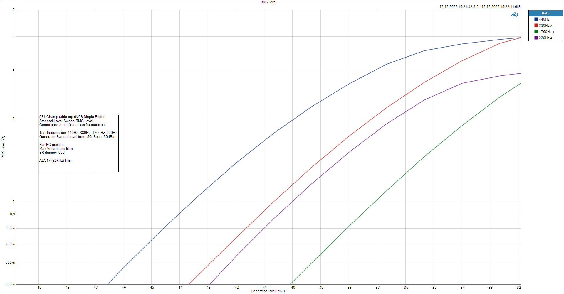
Stepped Level Sweep RMS Level
THD+N vs. Measured Level
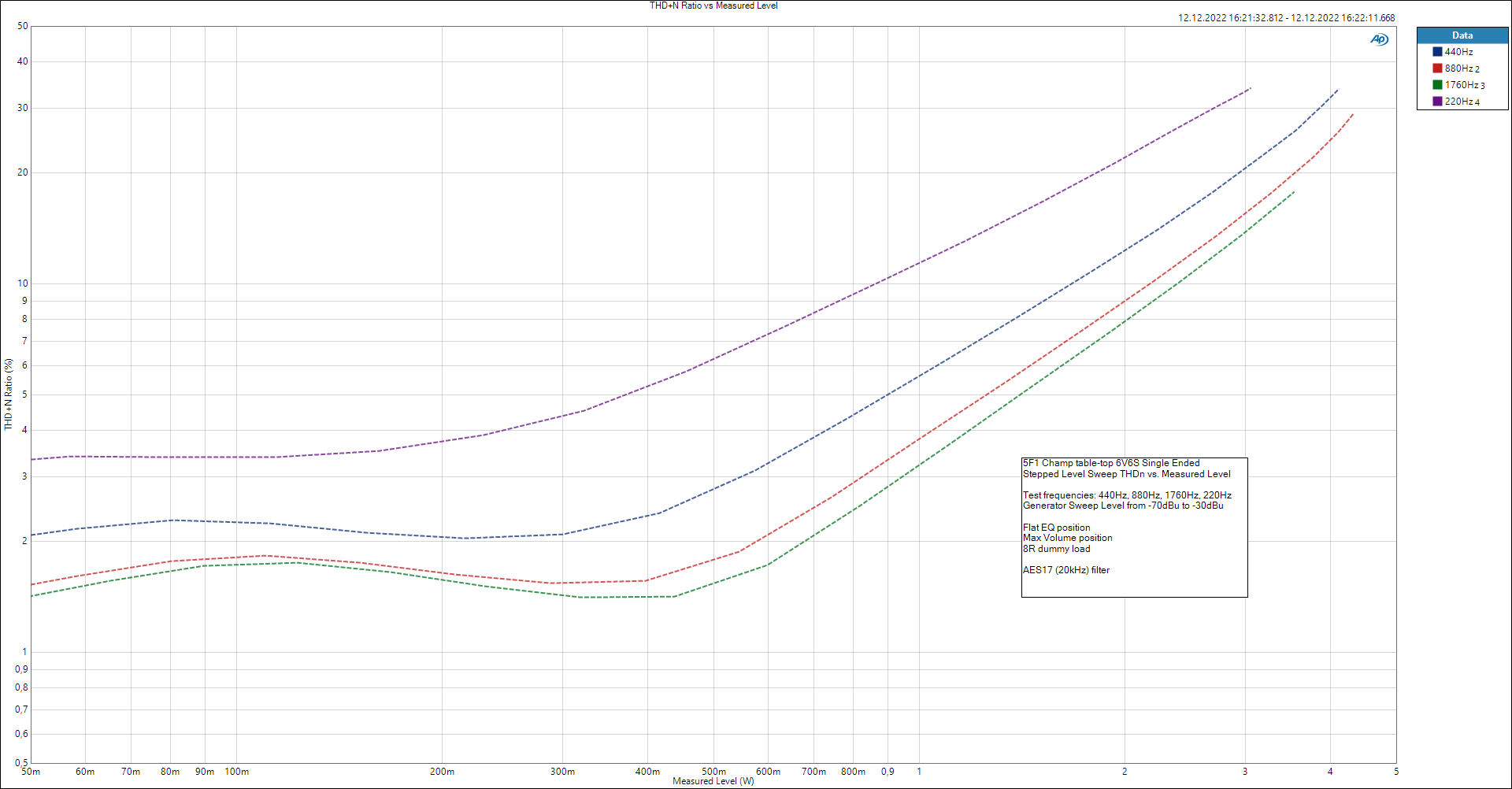
Stepped Level Sweep THDn vs. Measured Level
FFT
FFT @ 440Hz

FFT @ 440Hz
FFT @ 1kHz
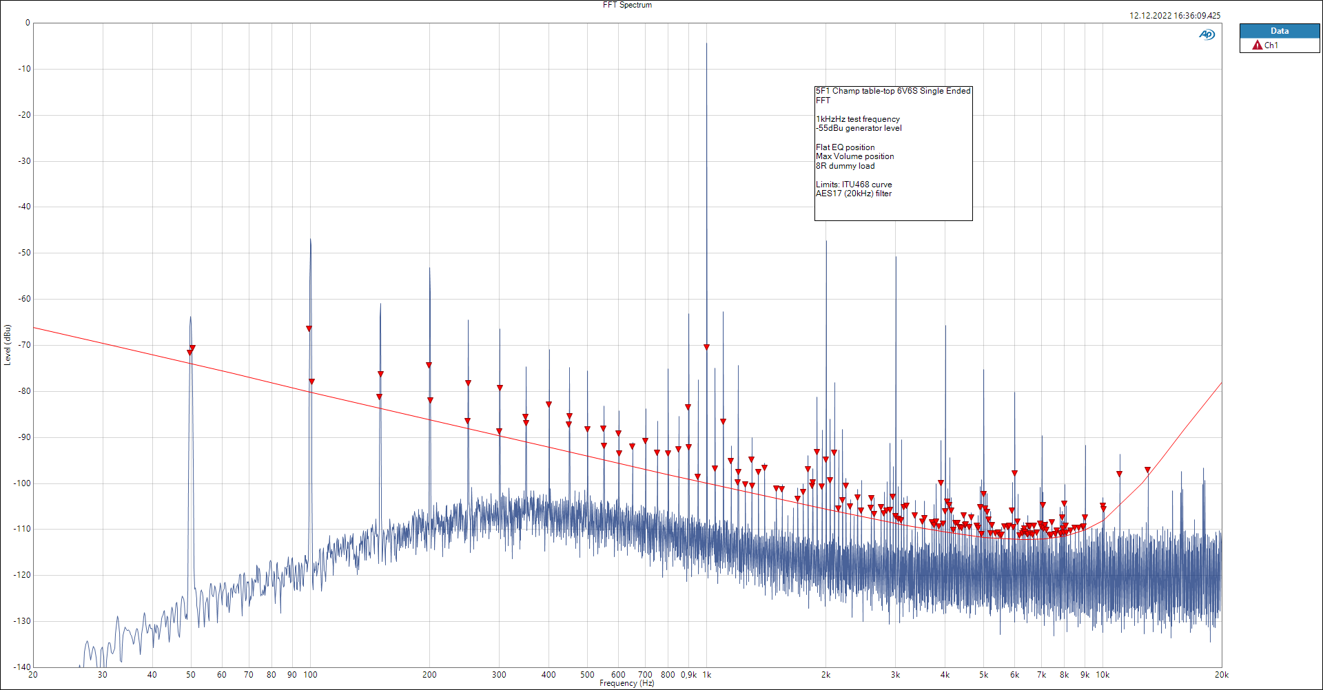
FFT @ 1kHz
FFT Noise Floor
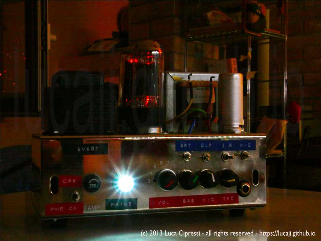
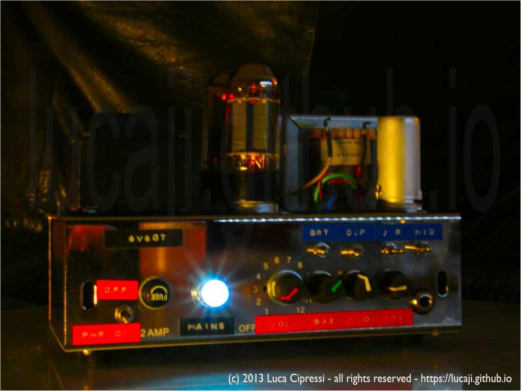
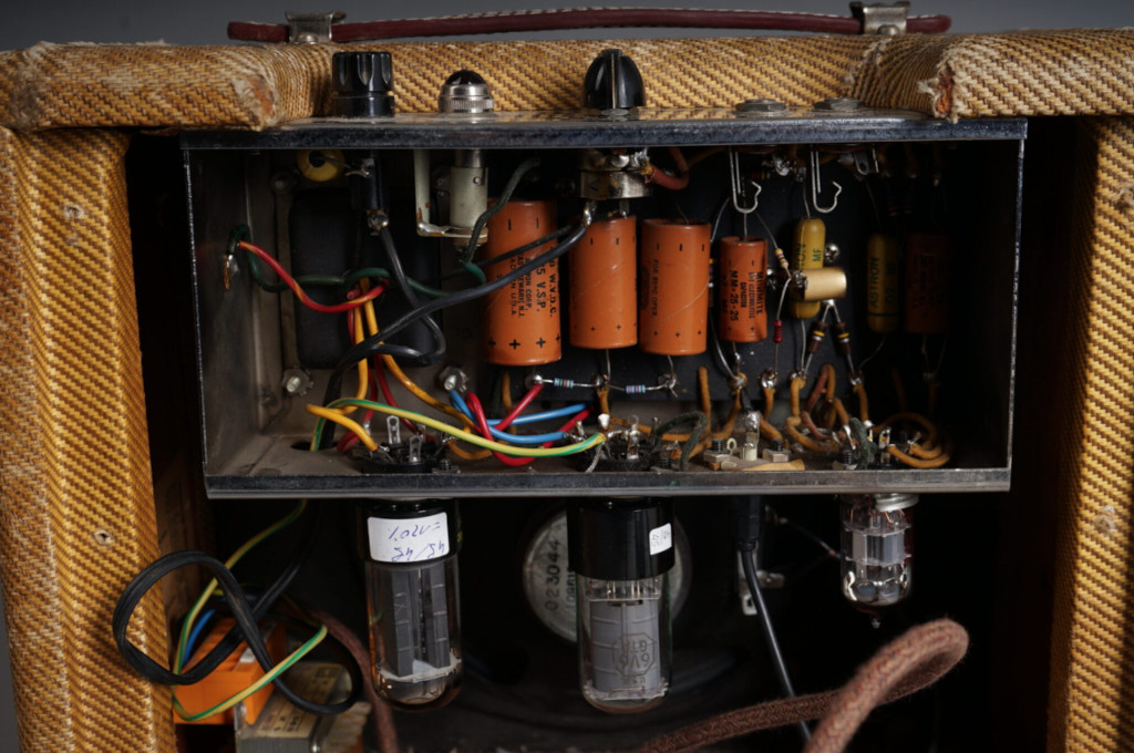
Fender Champ-Amp 5F1 1957
The Fender Champ was a guitar amplifier made by Fender introduced in 1948 and discontinued in the early 80s. I could put my hands once on an authentic Fender Champ-Amp (just like the one in the gallery below) from the late ’50s and I was immediately fascinated by its simple construction and characteristic sound.
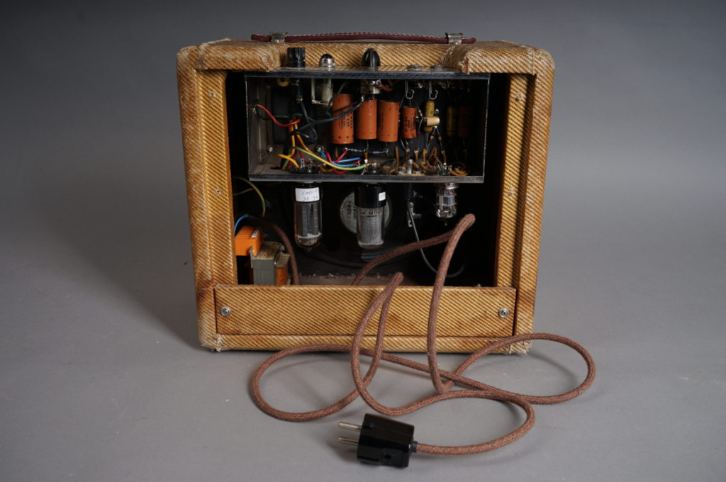
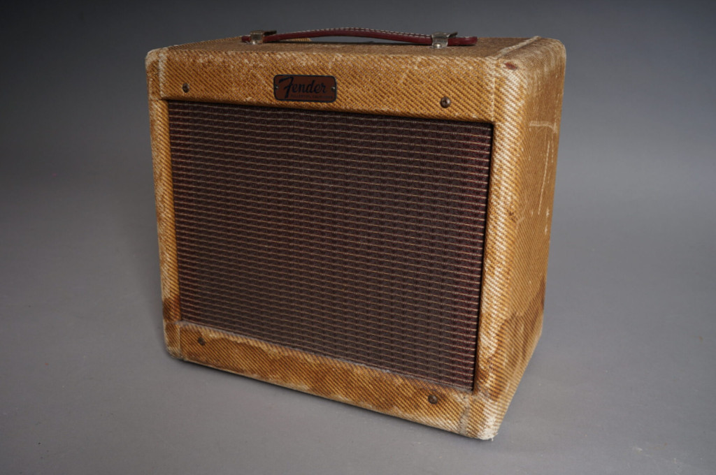
Here I collected some information about that original series.
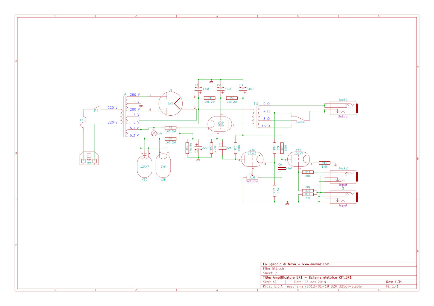
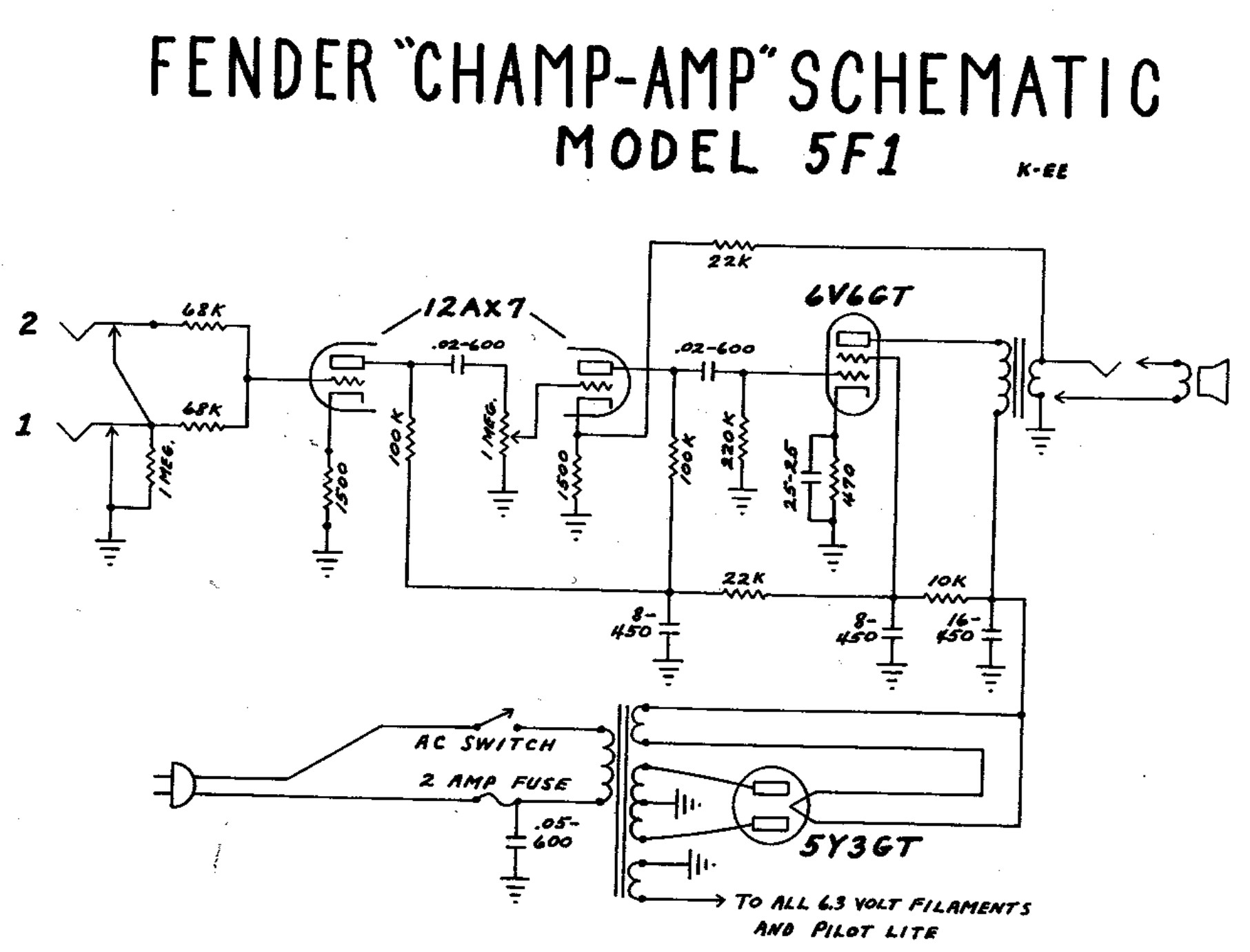
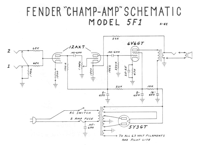
Fender Champ-Amp 5F1 original schematic
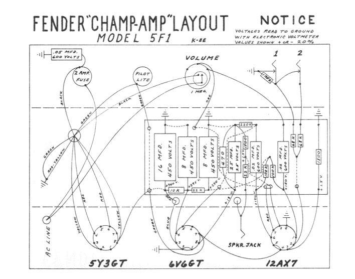
Fender Champ-Amp 5F1 original assembly layout
The power stage circuit is single-ended class A originally equipped with a 6V6GT tube. Five watts of output power without any tone-control circuit relegated this amp to be usually used in recording studios.
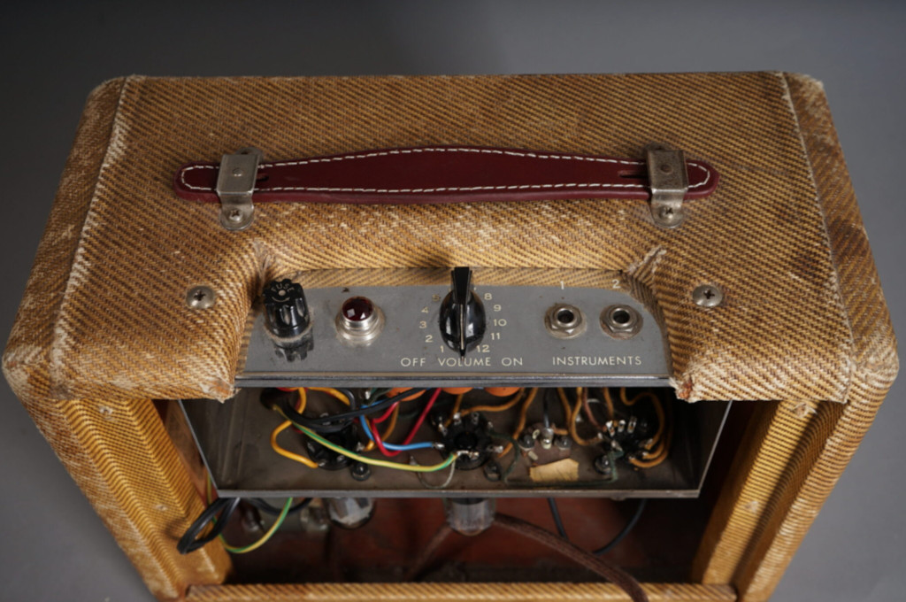
Input stage
There are two input jacks available, for low and high impedance sources. The 1M resistor when using the #1 input provides the grid return path for the input triode. When using the #2 input the 1M is shorted out and the grid return to ground becomes one of the 68K resistors with the other 68K resistor feeding the input in series. The grid is taken off at the mid point of the 2 x 68k resistor stack forming a 2:1 voltage divider causing a -6dB signal level drop.
6V6GTA vs 6V6SJJ
The original 6V6 is a tetrode introduced in July 1939, with two grids on top of the anode and cathode, and it is a scaled-down version of the 6L6 power tube introduced in April 1936. It was available in glass (GT) and metallic casing.
| Introduction date | 10 July 1939 | | Base | Octal (Int.Octal, IO) K8A, USA 1935 (Codex=Udb) | | Heater (filament) | 6,3V 450mA | | Heater warm-up Time (average) | 11 s | | Heater-Cathode Voltage Peak | ± 200V | | Heater-Cathode Voltage Average | ± 100V | | Direct Interelectrode Capacitances (approx.) | | | Grid No. 1 to Plate | 0.7pF | | Grid No. 1 to Cathode, Heater, Grid No. 2, and Grid No. 3 | 9pF | | Plate to Cathode, Heater, Grid No. 2, and Grid No. 3 | 7.5pF |
6V6 in class A (single-ended) amplifier configuration
| MAXIMUM RATINGS | | | Plate Voltage | 350V | | Grid-No.2 (Screen-Grid) Voltage | 315V | | Plate Dissipation | 14W | | Grid-No.2 Input | 2.2W |
| TYPICAL OPERATION | | | Plate Voltage | 250V | | Grid-No.2 Voltage | 250V | | Grid-No.1 (Control-Grid) Voltage | -12.5V | | Peak AF Grid-No.1 Voltage | 12.5V | | Zero-Signal Plate Current | 45mA | | Maximum-Signal Plate Current | 47mA | | Zero-Signal Grid-No.2 Current | 7mA | | Plate Resistance (Approx.) | 50KOhm | | Transcoductance | 4100umho | | Load Resistance | 5KOhm | | Total Harmonic Distortion | 8% | | Maximum-Signal Power Output | 4.5W |
| CHARACTERISTICS (Triode Connection) | * | | Plate Voltage | 250V | | Grid-No.1 (Control-Grid) Voltage | -12.5V | | Amplification Factor | 9.8 | | Plate Resistance (Approx.) | 1960Ohm | | Transconductance | 5000umho | | Plate Current | 49.5mA | | Grid-No.1 Voltage (Approx.) for plate current of 0.5mA | -36V |
- Grid No.2 connected to plate.
Here are the diagrams from the 6V5S datasheet, that are more of interest unless you have the real vintage ones.
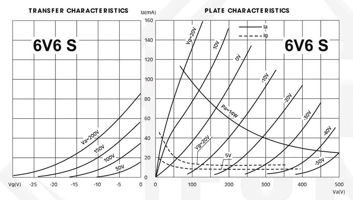
6V6S Curves
Equivalents: 6V6GT = 6П6С = VT-107A = CV511 = GT6V6 = 6V6GT/G = 6AY5 = 6V6_DDR