The Leslie Speaker
Article from ELECTRONICS Australia, March 1968
This article explains the principles behind Leslie-type loudspeakers and goes on to describe the construction of a generously proportioned system intended for use with a home constructed electronic organ. The article could provide the starting point from which individual readers could build up a rotating loudspeaker system to suit their own particular requirements.
Rotating System Loudspeakers for Electronic Organs
The most obvious and the routine method of radiating sound from an electronic organ is by means of one or more loudspeakers, suitably and conventionally baffled. In a single-unit instrument, the loudspeaker(s) are mounted behind cutouts, usually in the front panel below the keyboard and above the pedal clavier. While compact and convenient, this arrangement usually suffers some limitation in the effectiveness of the baffling which can be provided and the efficiency with which the sound can be propagated.
A logical “next step” in improving the performance of an electronic organ is to associate with it a generously designed remote loudspeaker system, which can provide good fundamental bass output and which can propagate the sound from a position in the building where it will be heard to advantage, and enrich itself with natural re-verberation.
Where the basic organ makes available its different voices from two or more channels, additional remote loudspeakers may be used, with or without supplementary amplifiers, dispersion of sound sources, more akin to what occurs naturally with pipe instrument.
Despite such measures, a charge levelled against electronic organs is that, while large amplifiers and elaborate loudspeakers can make them loud, the basic tone structure is too simple and too rigid, particularly where the generator system employs sequence of frequency-locked dividers. “interest” which is present when the sound is being built up from a large number dispersed and independant pipes, which are nominally in tune but not phase locked
The problem has been countered in clectronic organs by the use of separate oscillators in a limited number of designs, by the free use of variable-speed variable-depth vibrato and/or tremolo, and by the use of synthesised echo (reverberation). With such resources, good design and good playing technique, electronic organs can produce music which is appealing enough to have ensured their very wide acceptance in home, entertainment, and church situations.
However, over and above these largely electronics measures to add variety and interest to electronic organ sound, there has been wide adoption of the principle of feeding art of the sound to a loudspeaker system whose sound dispersion pattern is costantly being changed by actual physical rotation of the sound source.
One such system, which received a lot of early publicity, was the “Gyro” loudspeaker marketed by the Allen Organ Company. Externally, a typical Gyro cabinet appeared to be a fairly conventional open-backed unit, with loudspeakers radiating through a front fret. Behind the fret, however, a large circular flat baffle was arranged to spin on a stout supporting spindle. Mounted on the baffle, 180 degrees apart and carefully balanced were (or are) two 8-inch loudspeakers, receiving drive from the amplifier through a pair of slip rings. A motor inside the cabinet drives the spindle through suitably proportioned pulleys so that the loudspeakers can be spun as they radiate the organ sound.
In spinning they introduce “Doppler” effects which cause the sound as heard to be periodically raised and lowered in pitch as the cones alternatively and periodically vary the respective distances to the listeners’ ears. The same effect modulates the intensity and frequency of all natural echoes in the building so that the unit adds markedly to the complexity and potential aural interest of the radiated sound.
If such a loudspeaker system is used in addition to, but remote from a conventional fixed system, the rotating unit can provide the effect of an organ “chorus”, since there is a somewhat random lack of relationship between the two outputs, even though the signals may originate, in the first instance, from the same basic tone generators.
While we have elected to make initial reference to the Allen Gyro loudspeaker system, the name which is nowadays almost universally associated with “position modulated” sound sources is “Leslie” and organs are freely advertised as being fitted with inbuilt Leslie loudspeaker. Separate extension loudspeaker cabinets, with and without supplementary power amplifiers, and using the Leslie principle are marketed for use with existing organs. The units are either made by, or presumably manufactured under licence to, the Electro Music Company.
Wheter or not the originator of the principle would be happy to acknowledge them, commerical and amateur-built Leslie systems, so called, have taken many forms in recent years. To mention a few:
- A single, often smallish loudspeaker, with a minimum of baffling, supperted between two vertical spindles and projecting sound from both faces of its cone as it spins.
- One or more loudspeakers in a dynamically balanced enclosure, again spinning on pivots at top at bottom.
- A fixed conventional loudspeaker facing upwards or downwards, with the rear of the cone within a baffle houring and with the face radiating into a spinning, moulded horn, which sweeps the sound in a full horizontal circle.
- Similar to the above but using a flat or curved reflector plate to deflect the sound as the plate spins.
- A pressure transducer mounted vertically and feeding its output through a gland into a pair of back-to-back expontential horns, which sweep the sound through a full circle as they spin.
- A conventional fixed loudspeaker mounted vertically and able to radiate a certain amount of sound directly from the rear of its cone. A spinning moulded horn directs the sound from the fron of the cone through a full vertical circle, creating a random interference pattern between the two sources.
Loudspeakers which actually spin are very effective in creating the desired result but they present problem in achieven dynamic balance; air pressure may distort the cone and slip-ring contacts carrying the audio drive current present a further potental reliability hazard. Mercury dip contacts have been used with some success but they must obviously be designed not to spill if the system is accidentally upended.
Because of these problems, preferences appears to have gravitated towards the fixed loudspeakers with rotating deflectors but even these call for very careful design and construction, particularly if they are to be used in a quiet domestic or church situation.
- The drive motor, belt and support bearings of the rotating system must be notably free from noise and rumble.
- The rotating system must be very accurately balanced.
- The rotating system must be designed so that the adjacent air rotates with it. If the rotating system behaves instead as a paddle, it will create disturbing noise as it puffs the air in and out of the enclosure openings. In addition, air loading on the rotating system will upset any pre-arranged dynamic balance.
The modulation rate most commonly sought is about 7Hz, the same nominal figure as for electronic vibrato and tremolo. With single rotating loudspeaker or paddles, the system needs simply to be stepped down by pulleys to operate at beween 6 and 7 revolutions per second, or about 400 rpm. In a few cases having symmetrical outlets 180 degrees out of phase, the required speed might be nearer half this figure.
Since a Leslie type system in itself achieves a vibrano-cum-tremolo effect, cauion is necessary in using it with electronic vibrato or tremolo provided in the organ circuits. If the two are synchronized, the result may well be an excessive total effect; if they are not synchronized, a vibrato-on-vibrato effect will be produced which may be more spectacular than pleasant to the listeners! In short, vibrato with Leslie is a technique that should be used cautiously - and sparingly.
An interesting possibility is to run a rotating system at a much slower rate, typically at, or slightly above, one revolution per second, using it to supplement the main loudspeaker system. While having less immediate impact than operation at the higher speed, the contribution can be subtle and agreeable and with greater freedom in the use of in-built vibrato.
Irrespective of rotational speed, however, an important aspect of all Leslie type systems is the proportion of the total output which is fed through them.
first reaction might be to construct a full-range rotating system and to feed through it the total output of the instrument - bass, middles and treble. In practice, the overwhelming auditory effect of so doing is to produce extremely deep vibrato-cum-tremolo, which may well be more immediately apparent than its other qualities. It may appeal to those who like deep vibrato and tremolo but certainly not to many others.
The genius of a rotating system is for it to be heard in conjunction with a fixed sound source, the two interacting to produce ever-changing sound interference patterns. The control facilities may well allow for a variation in the proportion of the output fed to the rotating system, without going to the extreme of cutting the fixed system altogether.
In the more usual form of Leslie type loudspeaker system, the frequencies below a 300Hz to 800Hz crossover are fed to a heavy duty fixed loudspeaker, mounted in a suitably designed and substantially conventional enclosure. Frequencies above the nominal crossover are fed to a much lighter rotating system, controlled by a switch giving as its functions; Stationary, Fast and (sometimes) Slow. Facilities may also be provided on the console to select the loudspeaker system in use: Main, Main+Leslie and Leslie only.
The significant point about the “Leslie only” in this arrangement is that it provides its own interplay between fixed and rotating sources. The fixed loudspeaker handles the full bass range and a significant proportion of the chord structures from the maunals. The rotating loudspeaker handles a large proportion of the sound from the top end of the manuals, along with overtones from lower-pitched chords. Thus “Leslie Only” does not mean “Rotating System Only” but a discrete mixture of fixed and rotational output.
At the same time, in the “Stationary” position, the Leslie system is available as a straight remote loudspeaker, capable of handling the full range of the organ.
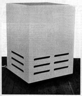
The rotating system pictured here was built up by one of our former staff members, Mr Brian Cleaves, for use with his own privately constructed organ. It is a full range system and, while it may not represent what other would-be constructors would necessariliy choose, it does illustrate contructional techniques applicable to the home workshop.
Since the loudspeaker is mounted in a vented enclosure, it is capable of producing a solid bass output, only vaguely “rotated,” the vent and its output being clear of the rotating mechanism. The system will take the full output of a spinet organ and Mr Cleaves has used it this way, with and without electronic vibrato, for extreme “popular” effects. Normally, however, it is used in partnership with the console loudspeaker as a “Stereo Chorus,” with facilities to cut the rotating system altogether, or to use it as the major source, with a minor contribution from the fixed system.
Alternatively, a fully baffled system like this can be used with a larger multi-channel installation to take the full output of flutes and tibias, as distinct from other voices, with control facilities for “Stationary,” “Slow” and “Fast.”
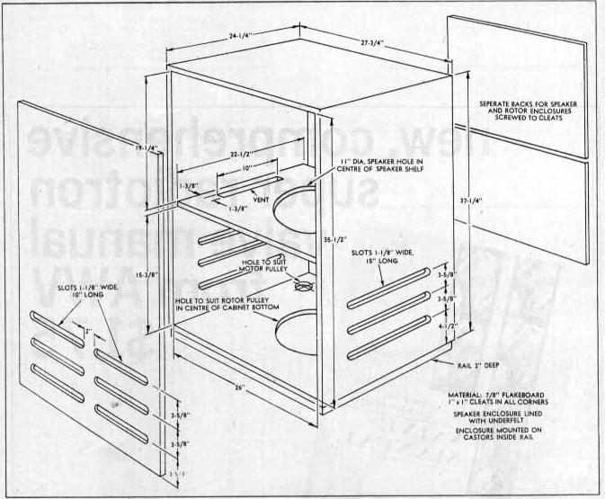
The enclosure, as illustrated is a large rectangular unit, built from 7/8-inch flakeboard and mounted on hidden castors for mobility. The fron, sides, top and bottom are permanently glued and screwed together, with frets cut in front and sides to provide an outlet for the sound.
Above the level of the frets, screwed firmly in place, is a horizontal shelf, which serves as a baffle for the loudspeaker, mounted cone downwards. Preparatory work on the shelf should be completed before it is fixed in position.
Access to the cabinet for fitting out is through the back, which takes the form of two removable panels screwed to cleats around all edges. One panel seals off the loudspeaker enclosure; the other gives access to the rotating mechanism. A single panel could be used if desired.
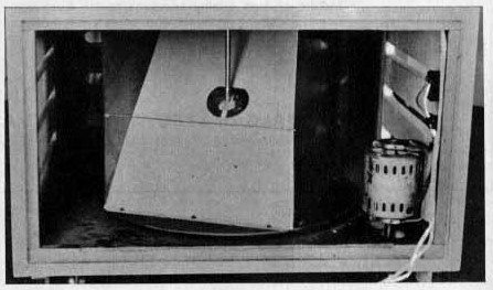
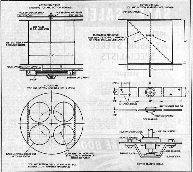
Basis of the rotating mechanism is a pair of 19-inch circles scribed and cut from 1/2-inch thick tempered composition board. A pattern of holes in the top board allows sound waves from the loudspeaker cone to pass down to the rotating assembly. The bottom board carries the drive pulley on its underside, attached by bolts and stand-off pillars.
Between these two boards is mounted two side panels made from 20 or 22-gauge mild steel sheet, with a lip turned outward at each end to permit them to be bolted to the circles of composition board just mentioned. The edges are tied together by a couple of thin traversing rods, to prevent any distortion or movement later, when then assembly is rotating.
The vane, which deflects the output of the loudspeaker, was made from 1/32-inch cardboard, screwed and cemented by its two ends to the circles of composition board. The vane forms an oblique angle with the rest of the assembly and, as it rotates, tends to deflect the sound waves from the loudspeaker cone through a full horizontal circle. While the panel may seem to be of unduly light material, it is in fact adequate for the purpose and, with a total weight of about 4-1/2oz, it does not detract much from the dynamic balance of the assembly Even so, individual constructors may elect to offset any residual umbalance by attaching something like a 1/2 to 3/4oz weight to each circle on the opposite side to the end of the cardboard vane.
The whole assembly described thus far must be provided with a central spindle, which, needless to say, must pass through the exact centre of the two composition board circles. If the assembly is symmetrical, as it should be, the spindle will be exactly equidistant from the metal cheeks and it will also pass through the exact centre of the cardboard vane.
A 3/8-inch diameter mild-steel spindle is suggested and the holes through the assembly should be drilled or filed to a tight push-fit. Where the spindle passes through the cardboard vane, it is suggested that a thin aluminium washer be prepared which will also grip the spindle and lie flat against the vane. Cement the whole assembly together with Araldite, or other similar preparation and, when complete, paint with dull black synthetic enamel. This prevents the rotating system from being visible through the vents or cloth and also seals the surfaces against the effects of moisture.
At the top, the spindle runs in a bearing attached to the loudspeaker baffle and on the centre line of the cone.
Another bearing, directly beneath the top bearing and hung from the floor of the cabinet, carries the spindle on the underside. In the original system, permanently lubricated bronze bearings were used, with a ball thrust arrangement at the bottom to take the vertical weight. The system has operated reliably for several months and should be adequate for a lengthy period of use in the home.
Ball bearings could be used instead, with some advantage, but precautions may need to be taken against the introduction of rumble. Rubber insulated bearing suggest themselves as a good choice.
The motor used in the original system was a capacitance start unit, actually salvaged from a worn-out electric typewriter. It measured 4in in diameter and 6in long and is rated at 35MH, 0.6A, 1425 r.p.m. It was complete with rubber mounting provisions, which would have been essential, anyway, to prevent vibration from being propagated via the cabinet panels. Smaller motors, from fans, etc., are not likely to be adequate for a system such as the one under disucssion, since they have insufficient starting torque.
The motor drives the rotating assembly through a belt and pully system on the underside of the cabinet. It is virtually essential to use a round section belt for the purpose, the engaging noise of a V-section belt making it far too noisy for this kind of work, by virtue of its propagation through the light rotating assembly.
To minimise the amount of air movement when the assembly is rotating, it is a good idea to slip a tube of light cloth over the rotating assembly using draw strings at top and bottom to hold it in position.
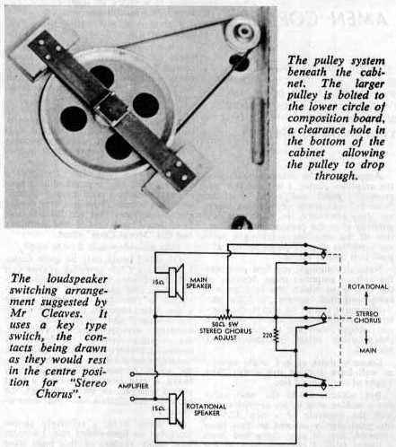
In the particalr combination of units in the system pictured, the acoustic efficiency of the Rola 12PEG loudspeaker in the rotating system was noticeably lower than that of the 12UEG loudspeaker in the console. This was due both to the nature of the loudspeakers and by the somewhat restricted radiation path through the rotating system. To achieve optimum balance with both loudspeakers on, it was necessary to reduce the level from the main console loudspeaker. Accordingly, a key switch (Ericsson N9302 or similar) was fitted to the console, together with a 50-ohm 5W potentiometer (Mallory VW50 or similar). These were wired as show in the accompanying circuit so that it was possible to select the rotating system only; or “Stereo Chorus,” involving both loudspeaker but with the facility for cutting back the loudspeaker in the console; and “Main,” the console loudspeaker only, with the limiting potentiometer out of circuit.