Restoration of an Old Open-Air Cinema PA
A Geloso G-225/A tube amplifier, from self-assembly kit to open-air cinema relic
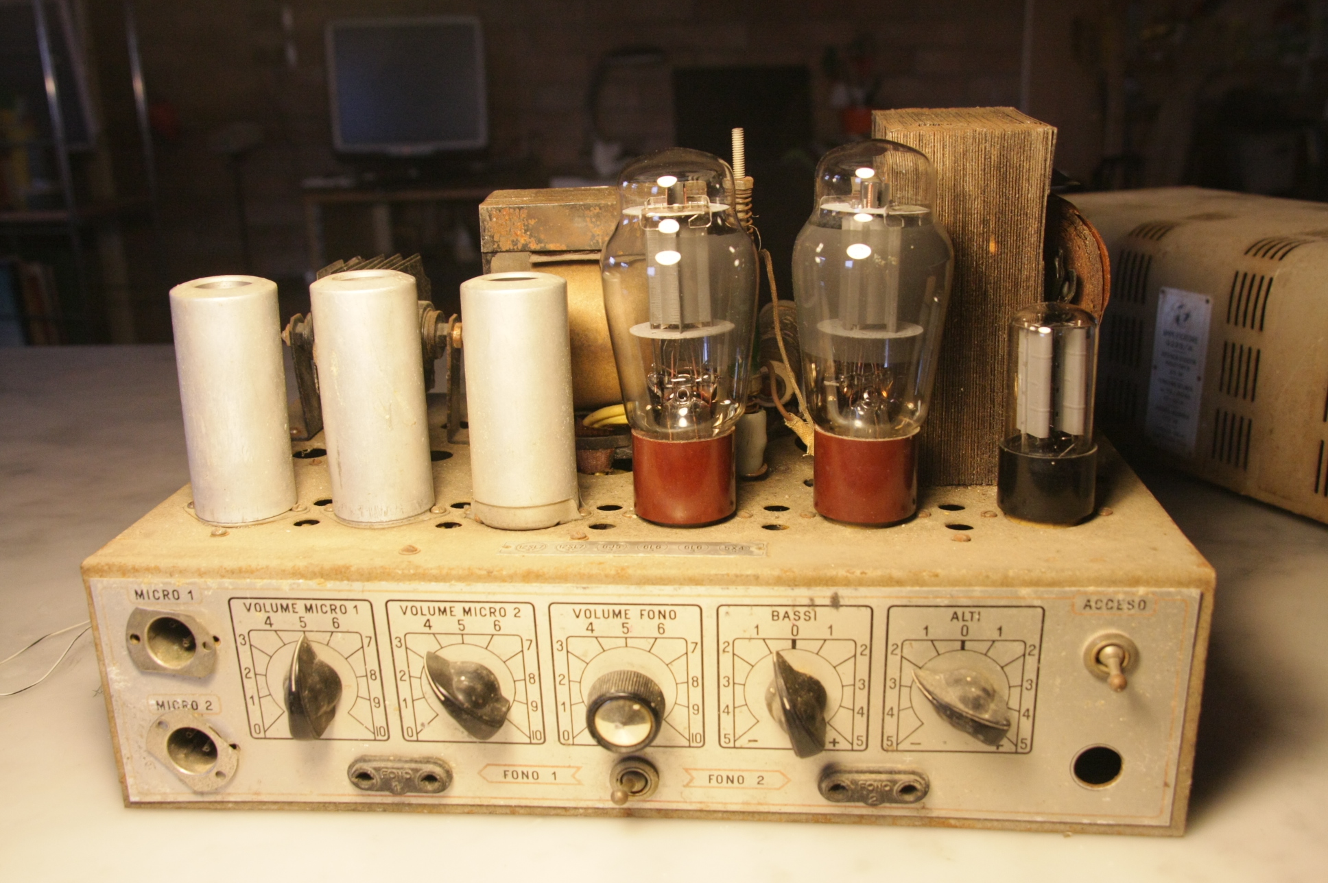
Back in its working days, this tube amplifier by GELOSO was used to amplify a small open-air cinema during warm Italian summer nights, somewhere between the 1970s and the late 1980s.
It was not a hi-fi amplifier, and it was never meant to be one. Its purpose was different: to make voices intelligible, music present, and film soundtracks audible across an outdoor space where people had gathered simply to watch a story unfold together. For spoken dialogue, narration, projected film sound, and the modest sound effects of that era, it was more than enough.
Today we are used to multi-channel systems, subwoofers, cinematic explosions, calibrated rooms, and endless discussions about fidelity. This amplifier belonged to another world. A world where the important thing was not the depth of the bass or the sparkle of the high frequencies, but the shared ritual of sitting outside on a summer evening, under the open sky, listening to a film through glowing valves and heavy iron transformers.
There is something deeply charming about that. This was public audio before it became spectacle: practical, robust, slightly imperfect, and full of character.
GELOSO
Geloso was founded in 1931 by Giovanni Geloso and became one of the most recognizable names in Italian electronics. The company produced radios, televisions, amplifiers, amateur-radio receivers, tape recorders, audio equipment, laboratory instruments, electronic components, and self-assembly kits. Its headquarters were located in Milan, at Viale Brenta 29.
From the beginning, Geloso was not only assembling finished products. The company also manufactured many of the components used inside them, and over time developed and patented numerous technical solutions of its own. This made the Geloso name familiar not only to ordinary consumers, but also to radio amateurs, repair technicians, students, experimenters, and electronics enthusiasts.
After the Second World War, Geloso expanded considerably. From the 1950s onwards, it became a point of reference for Italian hobbyists and for anyone interested in radio, audio, and practical electronics. Its products were appreciated for their solid construction, accessible prices, and a design philosophy that balanced professional usefulness with the curiosity of the amateur builder.
The Geloso catalogue was vast. Alongside radios, amplifiers, televisions, tape recorders, kits, and measuring instruments, the company also sold capacitors, resistors, potentiometers, switches, connectors, transformers, microphones, and other components. For many people, Geloso was not merely a brand: it was a doorway into electronics.
That is why this particular amplifier is so fascinating. It was sold as a self-assembly kit, and according to the rough estimate given to me by my friend, it was probably built around the mid-1970s. An exact date cannot be determined, but the story of the object is clear enough: someone assembled it by hand, installed it, and used it for years as the sound system of a local open-air cinema.
From Assembly Kit to Summer-Night Cinema
Some time ago, a friend of mine gave me this old cinema PA amplifier. It was in poor condition, but immediately intriguing. It had spent years in storage, with very little protection against humidity, dust, and all the slow destructive agents that are especially cruel to old electronic equipment.
The amplifier was not a factory-assembled unit. It had been built from a kit by my friend’s uncle, probably during the 1970s. That detail alone made it more interesting to me. A kit amplifier carries two stories at once: the story of the company that designed it, and the story of the person who patiently assembled it, solder joint after solder joint.
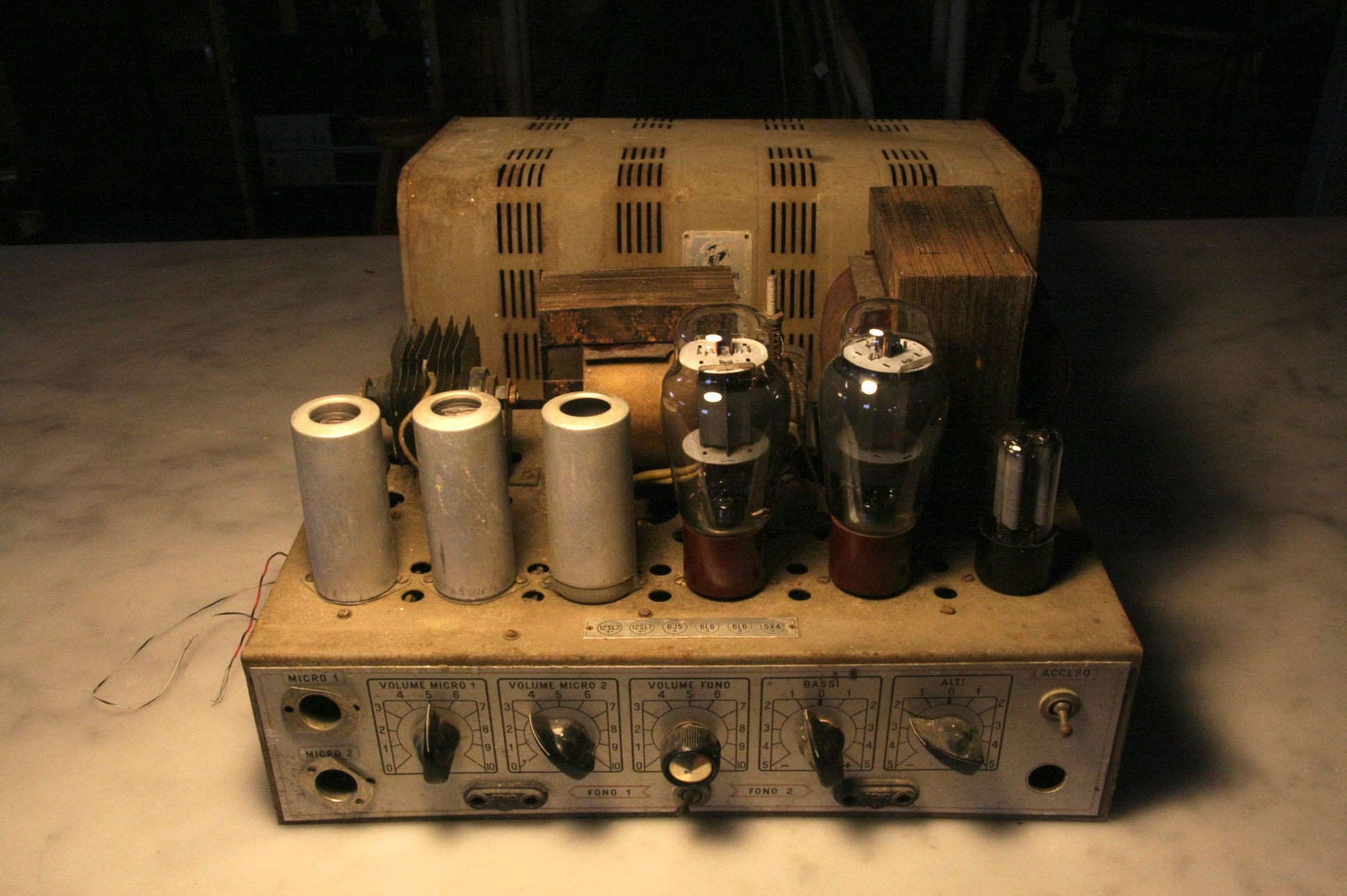
Here it is, in all its old and present glory: the GELOSO G-225/A.
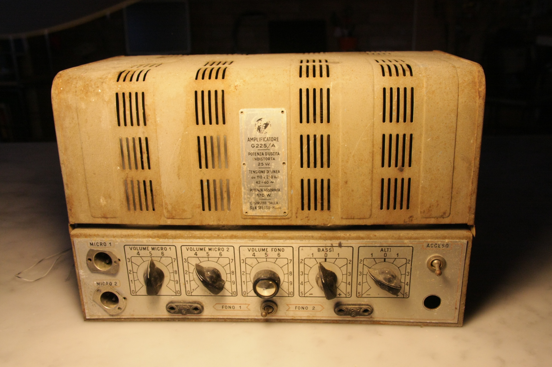
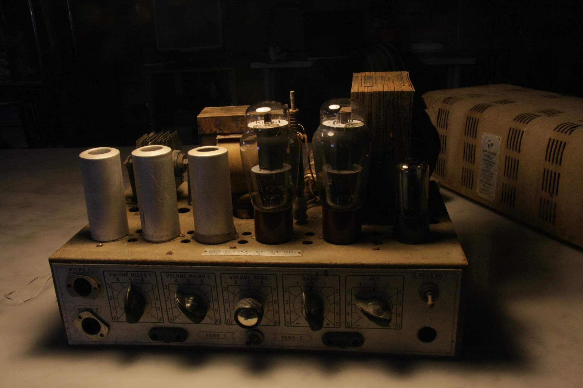
For a while, I tried to understand whether this small, heavy beauty could be brought back to life. Unfortunately, the truth soon emerged. Years earlier, my friend had already removed all the transformers. Not only had they been taken out of the chassis, but the transformer blocks themselves had been disassembled, with the iron laminations separated one by one.
The reason was humidity. The amplifier had been stored in a place where moisture had attacked the metal parts badly. The transformers were severely rusted; perhaps water had even reached the storage box directly. In an attempt to save them, my friend had submerged the parts in a corrosive bath and later tried to reassemble the laminated cores.
Sadly, the attempt did not succeed. The insulating enamel had been damaged, the laminations no longer aligned properly, and the original thickness and mechanical tightness of the transformer stacks could not be restored. In a tube amplifier, transformers are not decorative accessories. They are central organs: heavy, expensive, and electrically critical. Without them in proper condition, resurrection becomes far more complicated.
So I cleaned the amplifier as best as I could, admired its construction, photographed it properly, and eventually gave it back to my friend.
It is no longer amplifying summer films under the stars. Today it rests on a cupboard, silent but dignified, tying the room together in its own wonderful way.
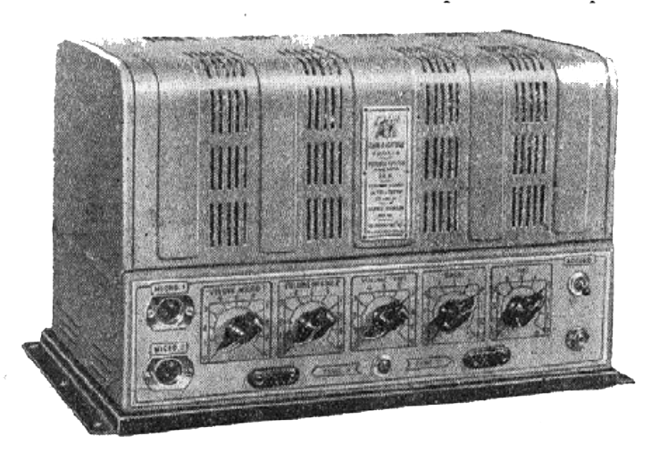
Geloso G-225/A
25 W modulated power — 6L6 push-pull class AB1 — 6 valves — 2 microphone sockets and 2 pick-up sockets with mixer — gain of 100,000 times the input signal.
The two microphone inputs and the two pick-up inputs, the three volume potentiometers and two tone controls, the voltage selector, and the rationally arranged input and output connections, together with the possibility of mixing signals from different channels, made this unit adaptable to many different installations: from small indoor rooms to churches and cinemas whose capacity was even above the average for the period.
The 25 W of useful power actually available at the secondary of the output transformer were sufficient to feed a considerable number of loudspeakers and to allow a rational distribution of sound.
This characteristic made the amplifier particularly suitable for installations of above-average capacity, where high fidelity of reproduction — high for the time — was required.
In this unit, the amplification is as high as 100,000 times the input signal, while the noise floor was reduced to about 1/2500 of the output signal. These results were achieved through suitable design choices in the filter circuits and by heating the filaments of the two 12SL7-GT valves with direct current obtained from a dry rectifier.
Technical Data
- Nominal power: 25 W (+36.2 dB), 5% THD
- Peak power: 35 W (+37.7 dB)
- Microphone sensitivity: 4 mV (-85.8 dB), Z = 1 MΩ
- Microphone gain: +122 dB
- Phono sensitivity: 180 mV (-53.1 dB), Z = 1 MΩ
- Phono gain: +89.3 dB
- Noise floor: -68 dB at maximum gain
- Frequency response: ±3 dB, 50 Hz to 10 kHz
- Output impedances in ohms: 1.25 - 2.5 - 5 (balanced) - 7.5 - 10 (balanced) - 14 - 18 - 30 (balanced) - 75 - 100 - 125 - 300 (balanced) - 350 - 400 (balanced) - 450 - 500 (balanced)
- Treble tone control: -15/+6 dB at 5 kHz; -21/+7 dB at 10 kHz
- Bass tone control: -10/+6 dB at 100 Hz; -18/+6 dB at 50 Hz
- Valves: 2x 12SL7-GT; 1x 6J5-GT; 2x 6L6-G; 1x 5X4-G
- Line voltages: 110 - 125 - 140 - 160 - 220 - 280 VAC
- AC power consumption: 170 VA
- Dimensions: 390 × 220 × 232 mm
- Weight: 13.5 kg
Power
The G225/A amplifier has an output power of 25 W. Distortion is clearly contained within a 5% limit. As the output power is reduced, the percentage of distortion also decreases rapidly, as shown in the explanatory curve:
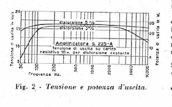
The peak power is 35 W (+37.7 dB). By replacing the normal transformer no. 5407, the G225/A can be used as a modulator for an RF final stage with 50 W of input power and 100% modulation, or up to 70 W with 80% modulation.
Hum and Noise Floor
Hum and background noise have been reduced to -68 dB at maximum output gain, that is, to about 1/2500 of the output signal.
Sensitivity
The sensitivity of the microphone channels is 4 mV, equal to -85.8 dB. With a signal of only 4 mV, the unit delivers full power, making the use of preamplifiers unnecessary even with less sensitive microphones.
For the phono channels, sensitivity is 180 mV, equal to -53.1 dB, which is sufficient even for the use of less sensitive magnetic pick-ups.
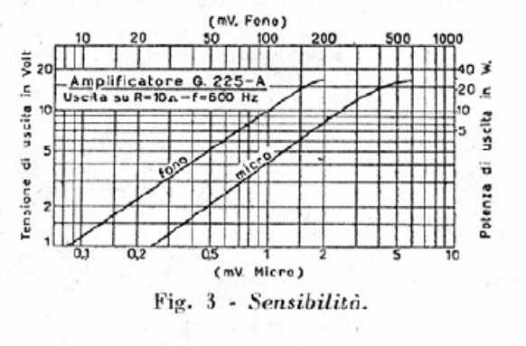
The design criterion behind the separation of the two microphone channels from the pick-up channel was to avoid, in the case of high-output pick-ups, saturation and distortion in the first valve, and to allow the signals of the two channels to be mixed as desired by means of their respective volume controls.
Input Circuits
In the G.225/A amplifier there are two microphone sockets and two phono sockets, all high impedance (1 MΩ).
There are three volume controls: one for each microphone and one for the pick-ups. These controls are separate and allow the signals from the various circuits to be mixed as desired.
The two phono sockets also make it possible to minimize pauses during record playback.
When using low-impedance microphones, such as ribbon or dynamic microphones, it is necessary, in order to obtain maximum performance, to couple these microphones through a suitably shielded step-up transformer.
Schematic
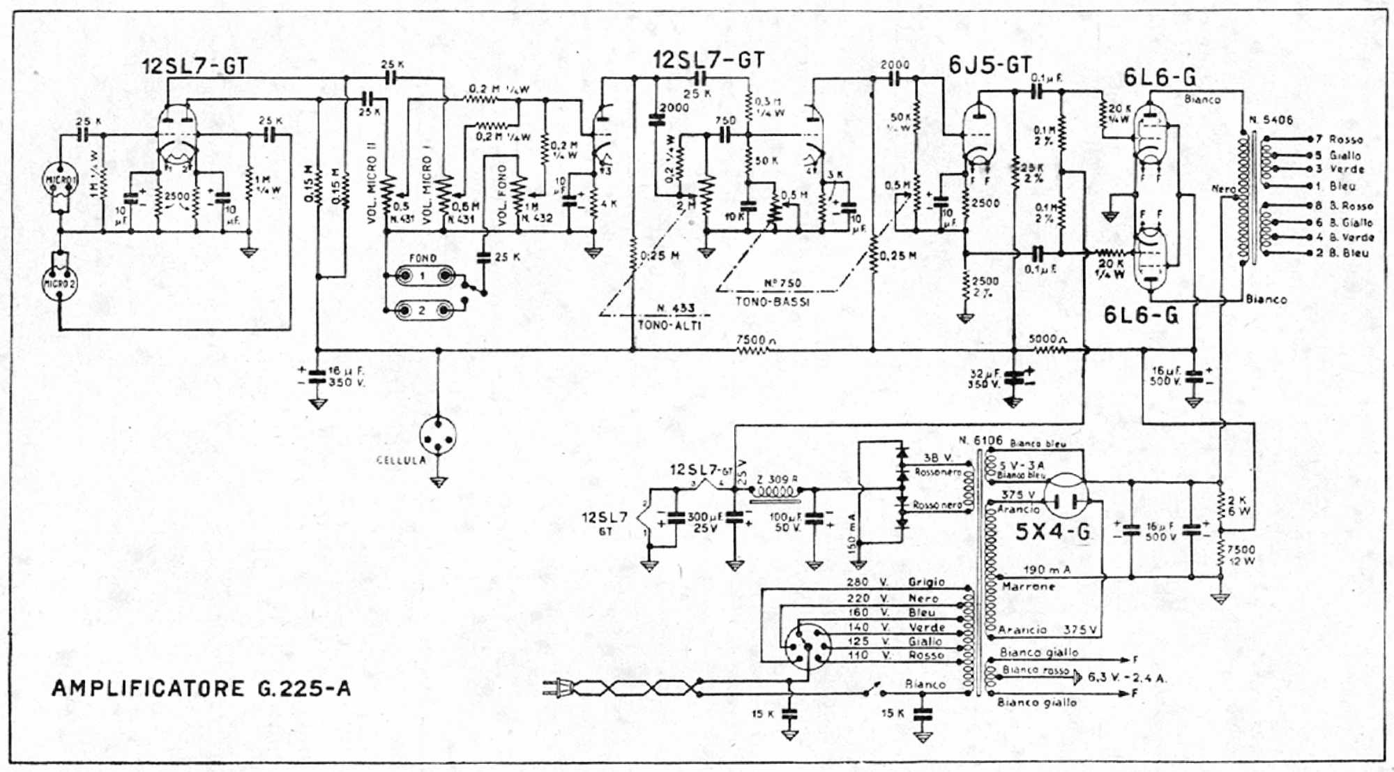
The input sockets of the two microphones are connected to the grids of the two triodes of the first 12SL7. The pick-up input is applied, through a switch, to the grid of the first triode of the second 12SL7.
The coupling between the two triodes of the first 12SL7 and the second 12SL7 is resistance-capacitance coupling, with special arrangements to allow the mixing of the two microphones and of one pick-up, and to adjust the volume of the individual channels separately by means of three potentiometers.
Intermodulation between the two microphone channels, with both microphones connected, is negligible.
The tone-control circuits are placed between the first and second triode of the second 12SL7, and between this valve and the 6J5 phase inverter. The high-frequency tone control uses a 2 MΩ logarithmic potentiometer, while the bass control uses a dual potentiometer: the 500 kΩ logarithmic section is used to eliminate the boost in the low notes caused by the 10,000 pF capacitor connected in parallel with it; the other 500 kΩ linear section has the task, by varying the grid resistance of the 6J5, of reducing the amplifier’s sensitivity to low notes.
The output stage consists of two 6L6 valves in push-pull configuration.
The power-supply circuit consists of a power transformer, a 5X4 full-wave rectifier, and the filter circuits.
The input capacitor is 32 uF, 500 V, and from this point the plates of the output stage are fed. A divider follows, formed by two resistors: one of 2000 Ω, 6 W, and one of 7500 Ω, 12 W. In parallel with the 7500 Ω, 12 W resistor there is a 16 uF, 500 V capacitor.
From this point in the circuit, the screens of the output stage are supplied. This is followed by a 5000 Ω resistor and a 32 uF, 500 V capacitor. Here the plate resistor of the 6J5 and that of the plate of the second triode of the second 12SL7 are connected. A 7500 Ω resistor and a 16 uF, 350 V capacitor follow.
From this point the plates of the first triode of the second 12SL7 and the plates of the first 12SL7 are supplied.
A rectifier circuit, with a selenium rectifier connected as a bridge, is used to heat the filaments of the first two valves and to provide the negative bias of the output stage.
The input capacitance of the heater circuit is 100 uF, 50 V. After a Z309R filter choke there is another 300 uF, 25 V capacitor.
At this point the bias voltage for the grids of the output stage is taken.
The filaments of the two 12SL7 valves, connected in series, are also connected after the choke. The filament of the first 12SL7 is toward ground, and another 300 uF, 25 V capacitor is connected in parallel with this filament.
The working voltages of the electrolytic and paper capacitors, and the power dissipated in the composition and wirewound resistors, are below their maximum operating limits, in order to offer the greatest guarantee of long service life for the installation.
Assembly
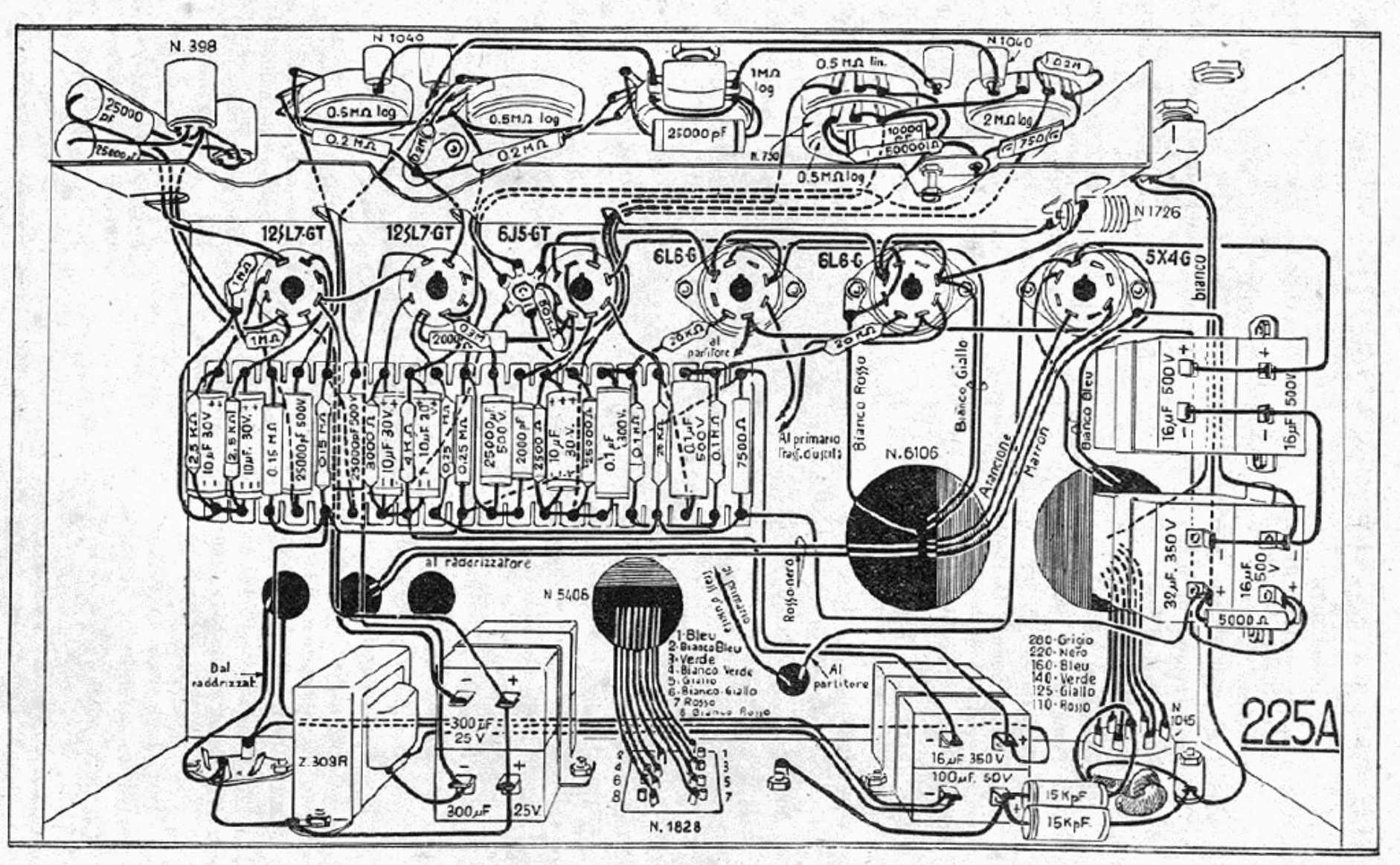
The assembly of the G225/A amplifier does not require any special precautions: it is enough to follow the indications of the electrical schematic and the assembly drawing carefully and intelligently.
First, the mechanical parts must be fixed to the chassis: valve sockets, microphone and phono connectors, potentiometers, chokes, transformers, and electrolytic capacitors.
It is necessary to observe the orientation indicated in the construction diagram, which provides guidance for the wiring layout.
First connect the parts closest to the chassis.
Pay attention when making the connections of the oxide rectifier and of the electrolytic capacitors, because an error could cause serious damage to the unit.
The wiring of the microphone sockets must follow the prescribed arrangement, standardized for all units.
To avoid the formation of rustling noises and background noise, take great care with the solder joints.
The protective shield for the input sockets must be fitted last.
The resistor board is prepared separately.
Once assembly is complete, check the insulation with an ohmmeter, especially the insulation of the hot sides from ground.
Insert the rectifier valve and check the voltage; insert the first two valves and check the negative voltage; then insert the remaining valves.
All voltages must correspond to those shown in the table below.
Voltage Check
After verifying that the connections are correct and continuous, proceed with the voltage check.
These measurements must be carried out both at the primary of the power transformer, to verify the mains voltage, and on the secondary and internal circuits of the unit.
For checking AC voltages, any moving-iron or rectifier voltmeter may be used, provided it is sufficiently accurate.
For measuring DC voltages, however, it is necessary to use a moving-coil voltmeter rated at 20,000 Ω per volt, since the values in the following table were measured with an instrument of those characteristics.
If the technician has an instrument with different characteristics, that is, with a different internal resistance, the possible voltage drop in the circuit resistors to which the instrument is applied must be taken into account, due to the greater current consumption of the instrument itself.
The measured voltages must be within 5% above or below the following values, provided that the mains voltage remains at the value indicated on the voltage selector. They must be measured between the valve pins and ground.
For normal operation, it may be accepted that the mains voltage varies by a maximum tolerance of 10% above or below the rated value.
VOLTAGE TABLE

High voltage
1st electrolytic . . . . . . . . . . . 400V
2nd electrolytic . . . . . . . . . . . 300V
3rd electrolytic . . . . . . . . . . . 280V
4th electrolytic . . . . . . . . . . . 270V
        / grid . . . . . . . . . . . . -25V
6L6-G   | screen . . . . . . . . . . . 300V
        \ plate  . . . . . . . . . . . 400V

        / plate . . . . . . . . . . .  215V
6J5-GT  |
        \ cathode . . . . . . . . . . . 57V

           / plate . . . . . . . . . .  90V
12SL7-GT   | cathode . . . . . . . . . 1.2V
           | plate  . . . . . . . . . 130V
           \ cathode  . . . . . . . . 1.6V

           / plate . . . . . . . . . . 160V
12SL7-GT   | cathode . . . . . . . . . 1.7V
           | plate  . . . . . . . . . 160V
           \ cathode  . . . . . . . . 1.7V

Negative voltage
1st electrolytic . . . . . . . . . . . -36V
2nd electrolytic . . . . . . . . . . . -25V
3rd electrolytic . . . . . . . . . . . -12.5V