DIY Tube Amp Builds: JCM800 and Fender 5F1 Clones 🎸
Marshall attack, tweed Champ simplicity, handmade chassis, and small-valve experiments
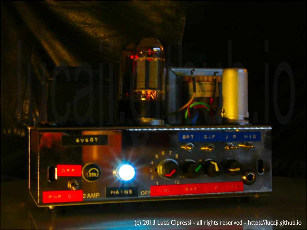
There are many ways to build a guitar amplifier. The final result depends on the time available, the budget, the parts already sitting in the drawers, and the amount of metalwork or woodworking one is willing to face before hearing the first note. One can buy an expensive kit, recycle a transformer from an old radio, order a ready-made chassis, fold one from sheet metal, or ask a skilled friend with proper workshop machinery to make a small run of enclosures.
That freedom is exactly what makes homemade tube amplifiers so addictive. The schematic is only the beginning. Around it there is a whole world of mechanical design, grounding strategy, thermal layout, front-panel lettering, speaker choice, cabinet resonance, paint, grille cloth, handles, feet, screws, logo plates, and the kind of tiny details that can make a build feel like a miniature custom-shop object.
For this series of builds I deliberately kept the electronic foundation simple. Almost everything started from two classic guitar-amplifier families:
- the Marshall JCM800 2204, the 50-watt master-volume high-gain head associated with hard rock and heavy metal;
- the Fender Champ 5F1, the tiny single-ended tweed amplifier that became a studio legend precisely because it is so direct, so small, and so easy to push into overdrive.
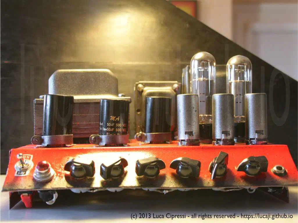
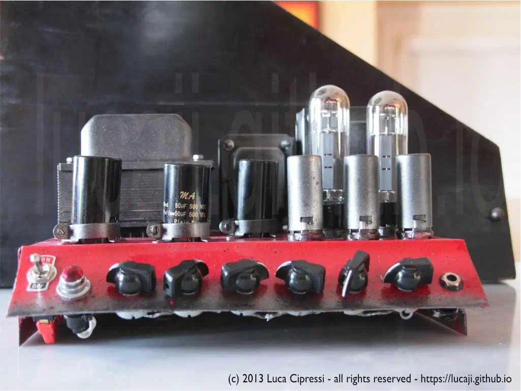
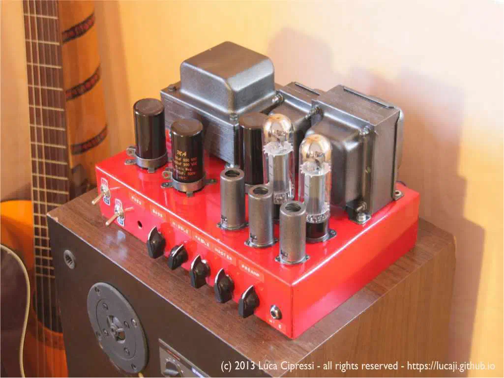
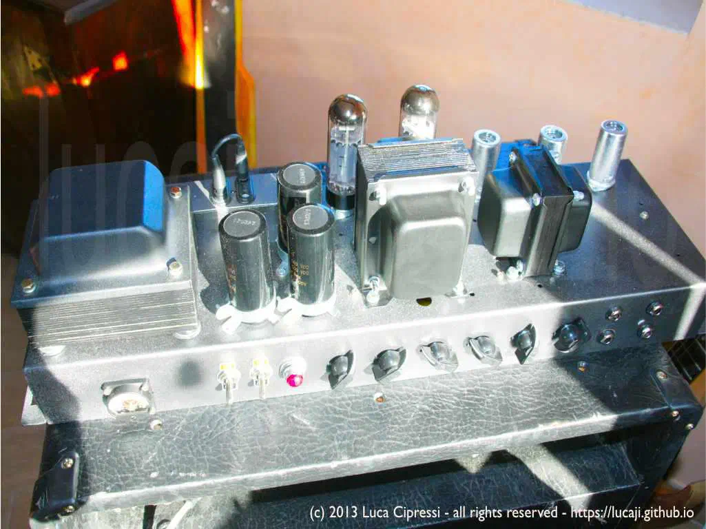
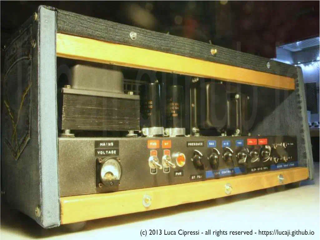
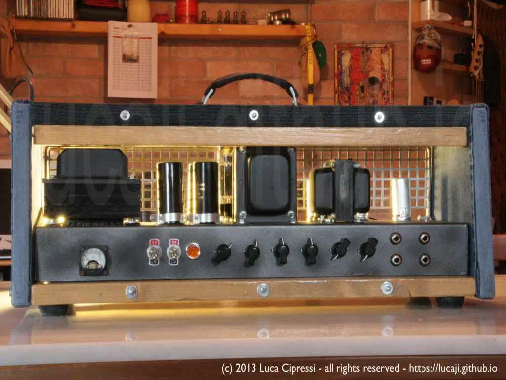
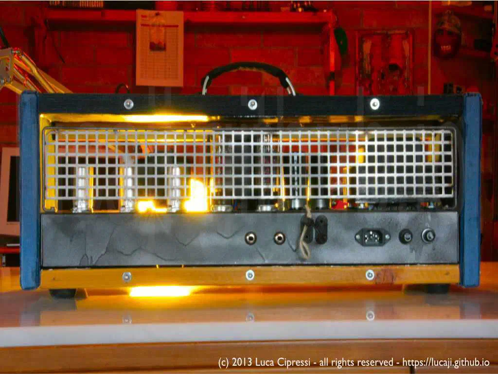
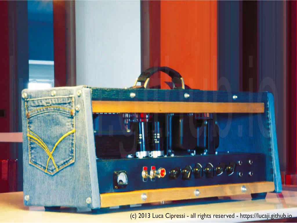
From these two basic schematics I built several physical and electrical variants: metal chassis, wooden headshells, compact table-top heads, a Champ-inspired amplifier with additional passive EQ filters, and even a denim-covered 5F1 cabinet made from old jeans, with the original back pockets placed on the side panels.
Building Tube Amps Builds Knowledge and Skills
- tube amplifiers contain lethal voltages, often several hundred volts DC;
- filter capacitors can retain a dangerous charge even after the amplifier has been switched off and unplugged;
- first power-up should be done carefully, ideally through a current limiter or Variac, with a proper dummy load connected;
- mistakes can destroy transformers, tubes, speakers, test equipment, or the builder;
- chassis work can be just as dangerous as the electronics: drilling, cutting, folding, filing, spray painting, and milling all require attention and protection;
- build time can become humongous and inversely proportional to playing time;
- build time may keep extending indefinitely because every amplifier invites “just one more improvement.”
The main advantages are worth the effort:
- you learn how to deal with high voltage circuits and safe discharge procedures;
- you see how physical phenomena — impedance, reactance, magnetic coupling, thermal drift, parasitic capacitance, feedback — become real and audible;
- you discover why lead dress, grounding, shielding, and transformer orientation matter as much as the schematic;
- you learn how different materials can be joined, glued, folded, drilled, painted, insulated, and finished;
- you collect a lot of practical tricks that never appear in simplified circuit diagrams.
At the end of the day you can proudly showcase your rig, let somebody else play through it, then clean up the workplace and get some sleep. The greatest thrill is always the same: turning the power switch on for the very first time on a new build. Every time.
Two Classic Starting Points
The Marshall JCM800 and the Fender 5F1 are almost opposite design philosophies.
| Feature | Marshall JCM800 2204 | Fender Champ 5F1 |
|---|---|---|
| Typical output power | about 50 W | about 4–5 W |
| Output stage | push-pull class AB | single-ended class A |
| Power tubes | 2 × EL34, or 6550 in some export versions | 1 × 6V6GT / 6V6S |
| Preamp tubes | 3 × ECC83 / 12AX7 | 1 × 12AX7 |
| Rectification | solid-state diodes | 5Y3 tube rectifier in the original design |
| Phase inverter | long-tailed pair | none required |
| Tone controls | Marshall treble/middle/bass tone stack plus presence | no tone control in the stock circuit |
| Distortion character | cascaded preamp gain, cold clipper, master volume | output-stage compression and small-amp breakup |
| Construction challenge | high gain, high power, careful layout | minimal circuit, ideal for learning |
The JCM800 teaches discipline: high gain, high voltage, push-pull symmetry, negative feedback, biasing, transformer placement, oscillation control, and the importance of clean wiring. The 5F1 teaches fundamentals: one preamp tube, one power tube, one rectifier, one volume control, no phase inverter, very few places to hide mistakes.
MARSHALL-ATTACKS!
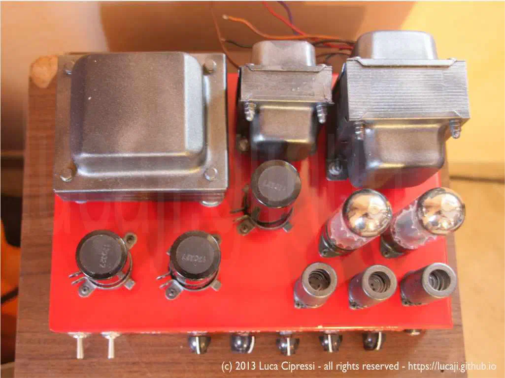
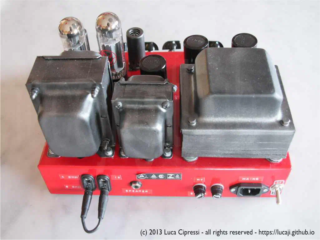
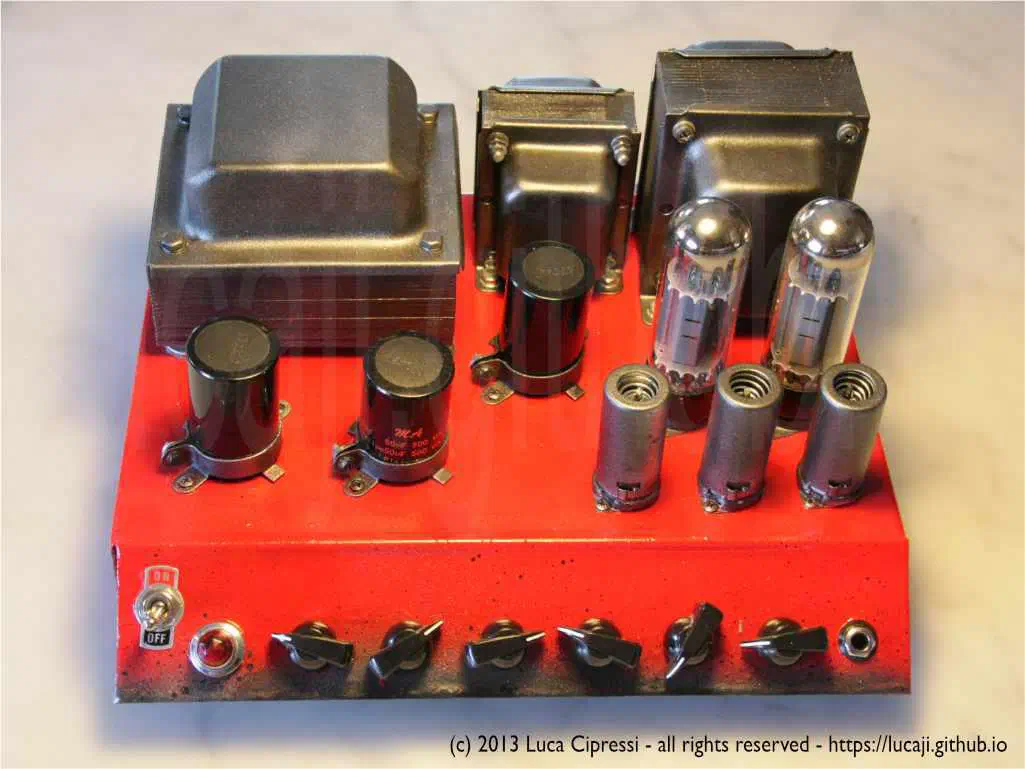
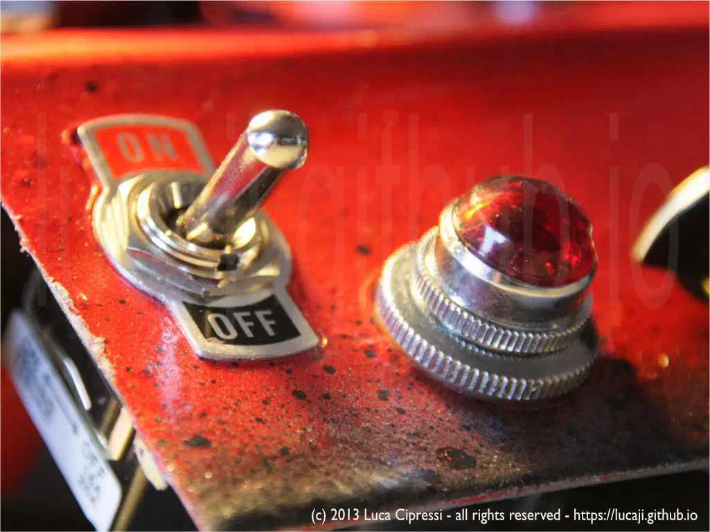
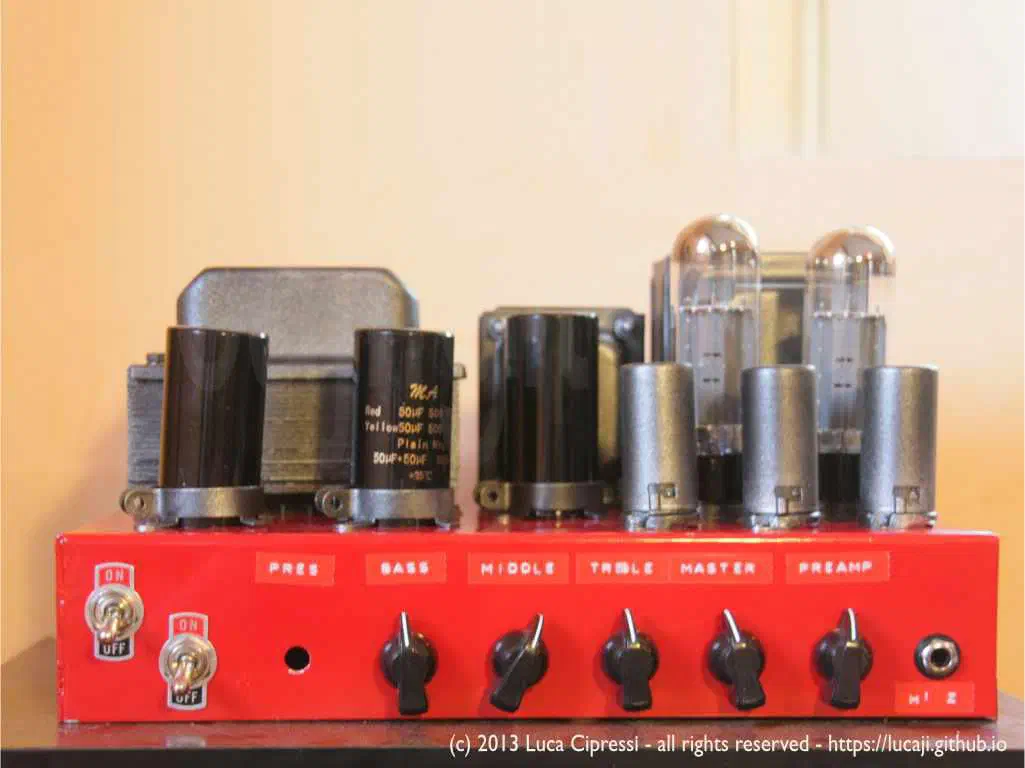
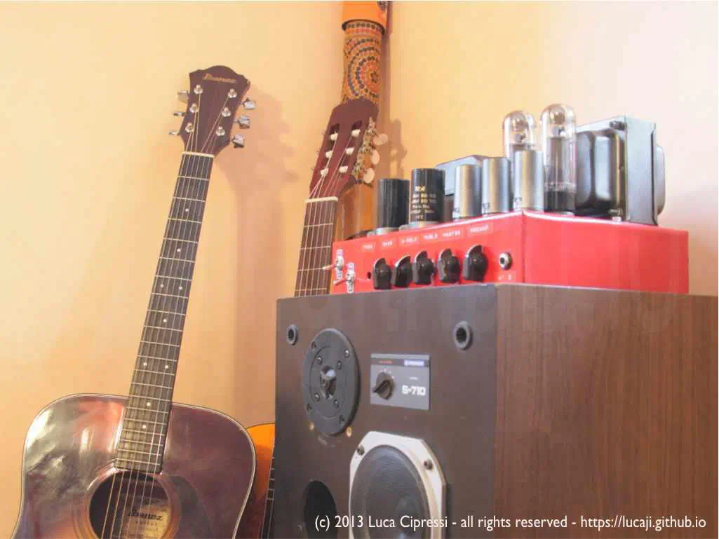
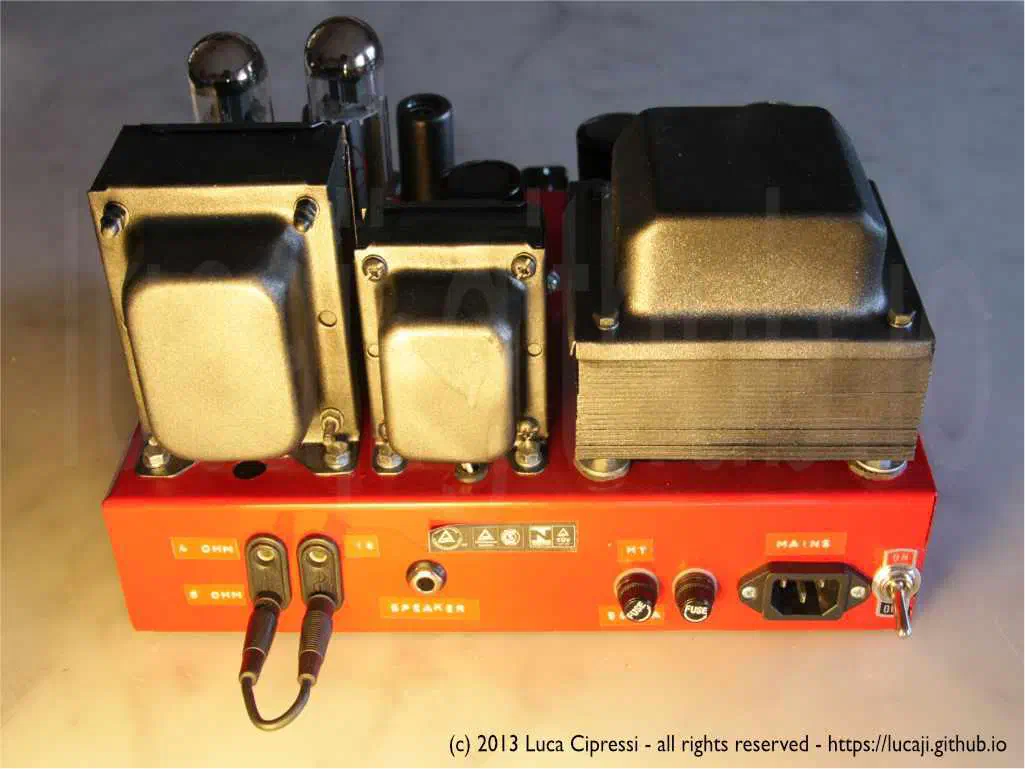
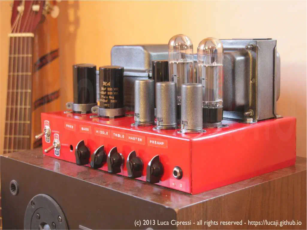
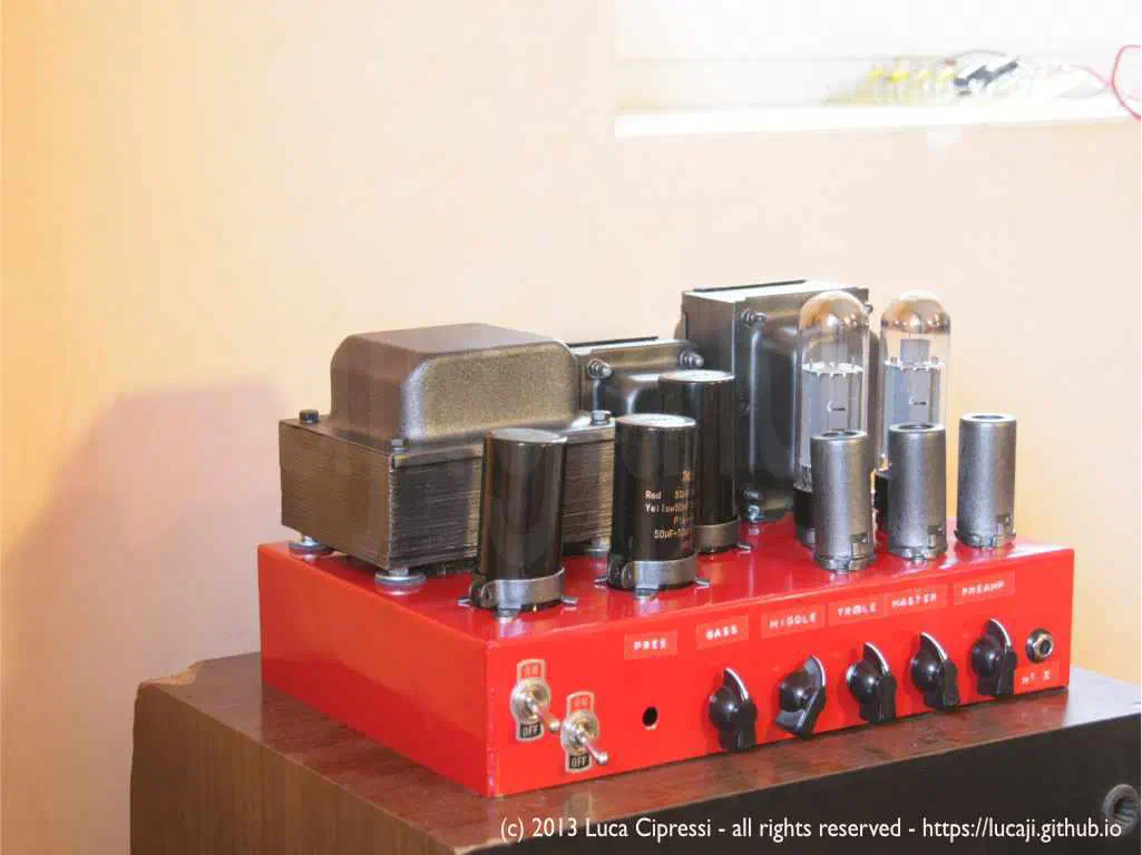
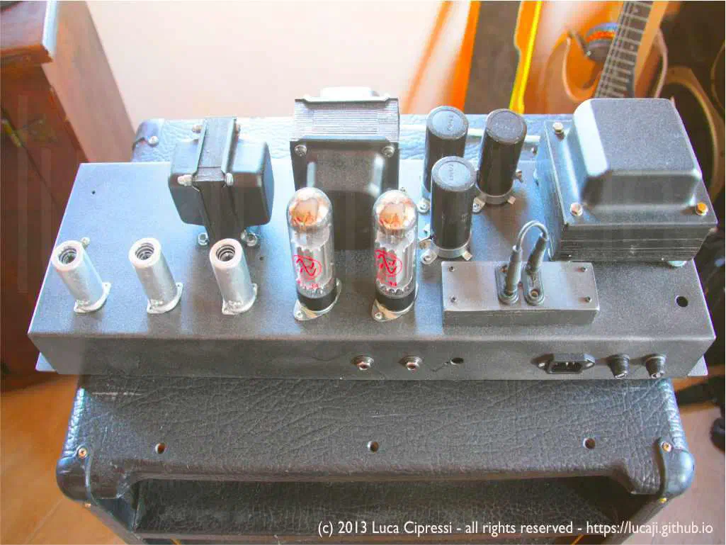
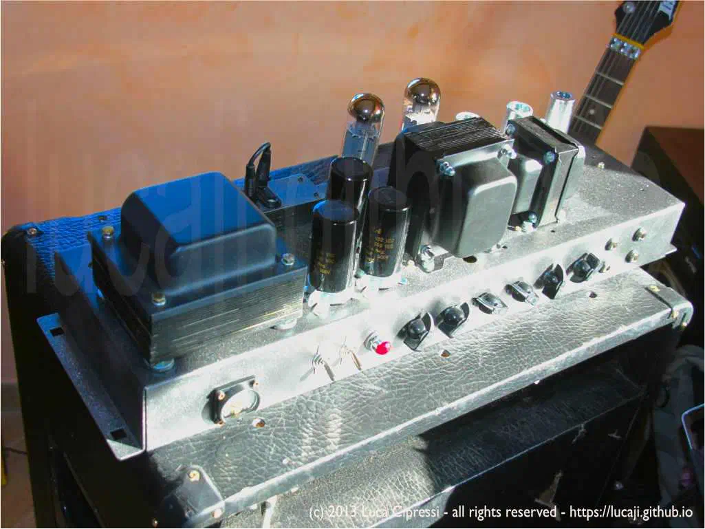
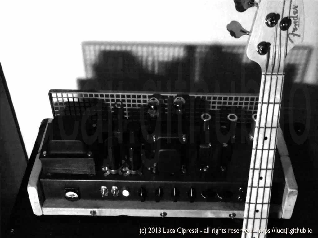
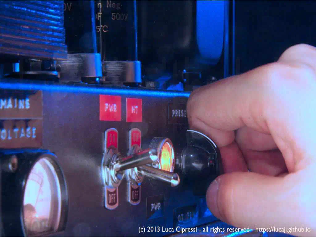
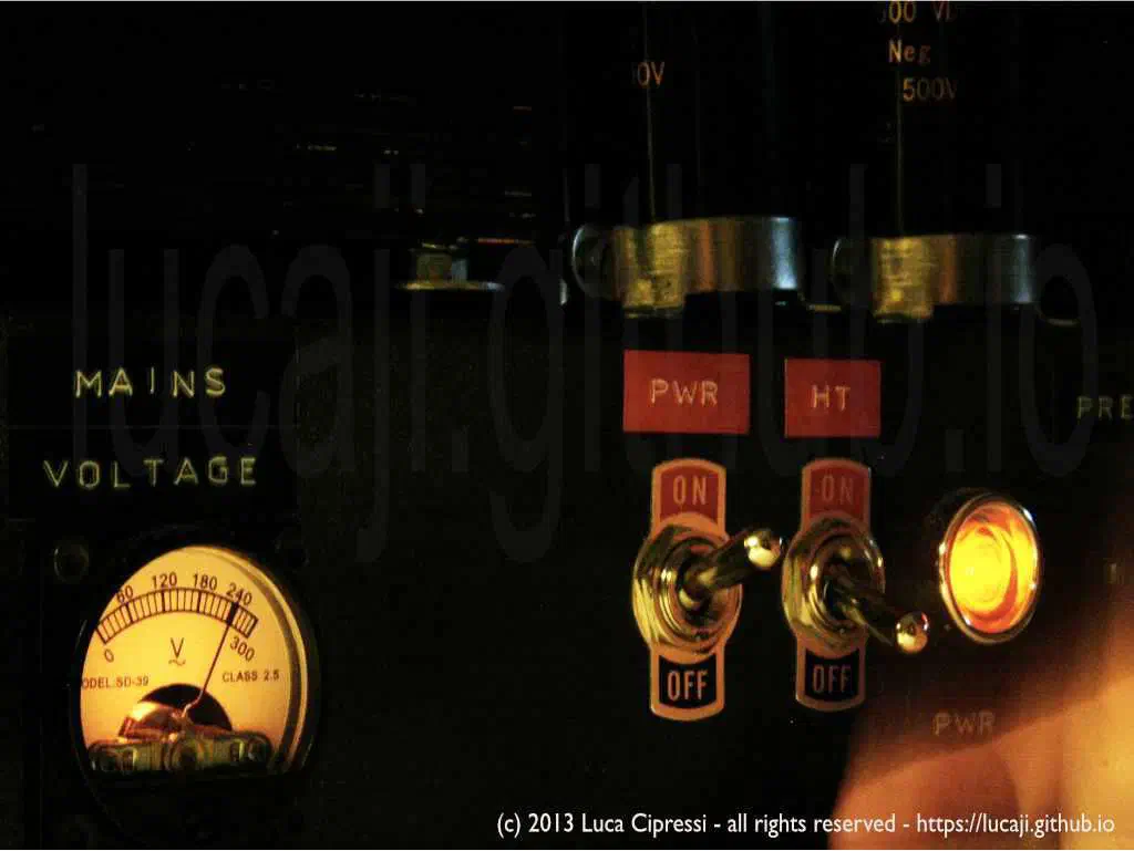
The following gallery displays some different builds inspired by the Marshall JCM800 , especially the 2204 Master Volume Lead model.
Why the JCM800 2204 Matters
The JCM800 name appeared in 1981, but the circuit family behind the first 2203 and 2204 models was already rooted in the late-1970s Marshall master-volume amplifiers. The 2203 was the 100-watt version, while the 2204 was the 50-watt head. The idea was simple and powerful: keep the aggressive Marshall voice, but add enough preamp gain and a master volume so that distortion could be achieved without running the power stage at full battlefield level.
The 2204 is not a modern channel-switching amplifier. It is still a relatively direct circuit, and that is part of its charm. It reacts strongly to the guitar volume knob, pickups, speakers, cabinet choice, and pedals placed before it. A boost pedal into the high-sensitivity input can move it from classic rock crunch to a much more saturated lead tone, while the low-sensitivity input can remain surprisingly clean and usable.
JCM800 2204 Signal Path
A simplified reading of the 2204 signal path looks like this:
-
High and low sensitivity inputs
The high input routes the guitar through an additional preamp triode before reaching the rest of the preamp. The low input skips that first gain stage and is therefore cleaner and less sensitive. This is not the same idea as the old four-input Plexi arrangement, where channels can be jumpered externally. -
First gain stage
The high input first hits one half of a 12AX7. In classic Marshall fashion, the early stages are deliberately voiced to keep the low end under control. Trimming bass early is crucial in a high-gain amplifier: too much low-frequency energy before distortion tends to become flabby, muddy, and unstable. -
Preamp volume / gain control
The preamp volume controls how hard the following stages are driven. In practice this is the “gain” control of the amplifier. -
Cold clipper stage
One of the defining sections of the JCM800 preamp is the cold-biased triode often called the cold clipper. Instead of using a more typical 1.5 kΩ cathode resistor, this stage uses a much larger cathode resistor, biasing the triode closer to cutoff. The result is asymmetrical clipping: one half of the waveform starts to flatten earlier than the other. This creates a distinctive harmonic structure and contributes to the JCM800’s cutting, vocal overdrive. -
Additional gain stage and cathode follower
After the cold clipper, the signal is amplified again and then sent to a cathode follower. The cathode follower does not provide voltage gain; its job is to present a low-impedance drive to the tone stack, preventing the tone controls from loading the previous gain stage too severely. -
Marshall tone stack
The familiar treble, middle, and bass network shapes the voice of the amplifier. The controls are interactive: changing one affects the apparent range and effectiveness of the others. In a JCM800, the midrange control is especially important because the amplifier lives in that aggressive guitar band between body, bite, and presence. -
Master volume
The master volume sits before the phase inverter. This placement allows the preamp to be driven into distortion while the power stage is held at a manageable level. It is not identical to a fully cranked non-master-volume Marshall, but it made high-gain Marshall sounds much more controllable. -
Long-tailed-pair phase inverter
The phase inverter creates two opposite-polarity signals to drive the two EL34 power tubes in push-pull. -
EL34 push-pull power stage
The 50-watt output stage is fixed-bias, class AB, transformer-coupled, and typically associated with EL34 tubes in European versions. Some export units used 6550 tubes, which can give a tighter and harder feel. -
Negative feedback and presence
A portion of the output transformer secondary is fed back into the phase-inverter area. This global negative feedback reduces distortion and tightens the response. The presence control modifies the high-frequency part of that feedback loop, changing the edge and attack of the power amp.
JCM800 Build Notes
A JCM800-style build punishes sloppy layout more than a Champ. There is enough gain for tiny wiring mistakes to become audible. The input leads should be short and shielded where necessary. Heater wires must be twisted and routed away from sensitive grids. The first preamp stage deserves special care, because any hum or noise introduced there is amplified by everything that follows.
The ground scheme also matters. A careless mixture of preamp grounds, power grounds, and chassis returns can create hum loops or make the amp unstable. I prefer to think of the layout as part of the circuit: transformers, sockets, jacks, pots, bus grounds, star points, shielded cable, and chassis contact points are not mechanical afterthoughts. They are the three-dimensional version of the schematic.
The power stage must always see a proper load. Testing a tube amplifier without a speaker or dummy load can generate damaging voltage spikes at the output transformer. For bench work I prefer a resistive dummy load of the correct impedance, followed by controlled measurements and only then a speaker test.
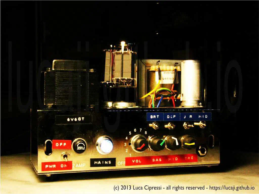
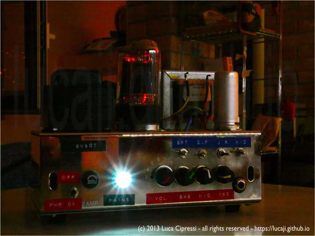
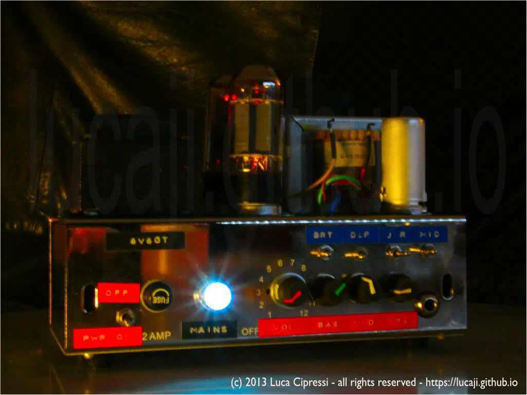
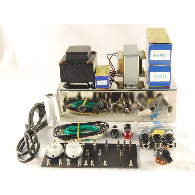
Fender Champ-Amp Table-Top
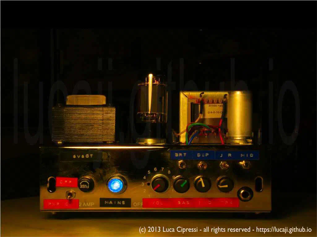
This build is my favourite, and I still plan to spend more time with it. The Champ is an ideal project for learning how tube amplifiers work, and it gives back a huge amount of satisfaction when playing through it. It is small enough to debug, simple enough to understand, and musical enough to justify all the time spent on metalwork and wiring.
Inspiration: VOX Night Train Form Factor
The inspiration for this build came from the VOX Night Train series, which caught my eye especially for its compact form factor, metallic lunchbox-style case, and perforated grille. The Night Train looked like a small piece of industrial design that also happened to be a guitar amplifier.
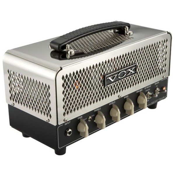
VOX Night Train - NT15H Head
The larger NT15H Night Train used a pair of EL84 output tubes and a pair of 12AX7 preamp tubes, delivering either 15 W or 7.5 W depending on the operating mode. It was much closer to the VOX family of push-pull British amplifiers than to a Fender Champ.
The smaller Lil’ Night Train reduced the concept even further. It offered about 2 W into 16 Ω, using two 12AX7 tubes in the preamp and a 12AU7 dual triode as the power tube in a small push-pull output stage.
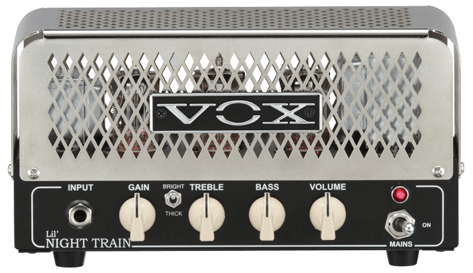
VOX LIL'Night Train
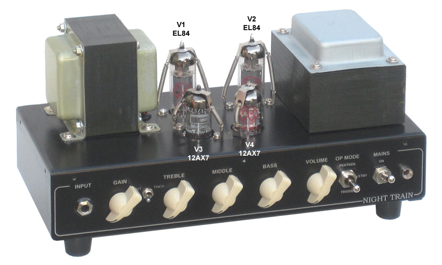
VOX Front
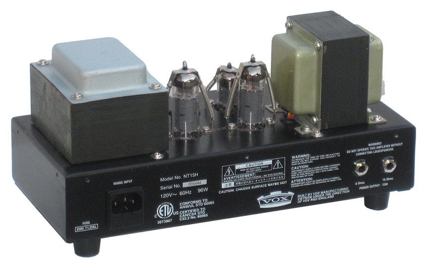
VOX Rear
What I borrowed from VOX was not the circuit topology, but the object idea: a compact table-top head with a visible metal cage, a practical handle, and a form factor that invites experimentation. Electrically, I remained closer to the Fender Champ-Amp philosophy: a simple single-ended power stage with a 6V6-family tube.
From Stock 5F1 to Table-Top Clone
The original Fender 5F1 has no tone control. That is part of its magic. The guitar, the volume control, the speaker, and the output transformer all become the tone circuit. For my table-top version, however, I wanted to take the original idea one step further and add passive tone-shaping filters while keeping the circuit simple.
These filters were not meant to turn the amplifier into a full blackface Fender, a VOX, or a Marshall. They were meant as small voicing options: gentle bass trimming before distortion, treble softening when the amp becomes too sharp, and midrange shaping to make the small power stage feel larger or more focused. Passive filters always lose some signal, so they must be placed thoughtfully. In a small amp this can actually be useful, because a few dB of attenuation can make the volume control more progressive and reduce excessive low-end drive into the 6V6.
Fender 5F1 Circuit Description
The 5F1 Champ is wonderfully minimal. A stock-style signal path is:
-
Two input jacks
The classic Fender high/low input arrangement uses 68 kΩ grid-stopper resistors and switching jacks. The high input presents a high impedance to the guitar and uses the two 68 kΩ resistors effectively in parallel as the grid-stopper path. The low input forms a voltage divider that attenuates the signal by roughly 6 dB and presents a lower input impedance, which can also darken the pickup slightly. -
First 12AX7 gain stage
The first triode amplifies the guitar signal. In the 5F1 this stage is biased in a conventional, relatively linear way, commonly with a 100 kΩ plate resistor and a 1.5 kΩ cathode resistor bypassed by an electrolytic capacitor. -
Volume control
The volume pot sits between the two triode stages. There is no separate gain and master volume arrangement: turning up the amp increases the drive through the whole circuit. -
Second 12AX7 gain/driver stage
The second triode provides more voltage gain and drives the 6V6 grid through a coupling capacitor. In the 5F1, this stage is also the point where the negative feedback loop returns. -
Single-ended 6V6 power stage
The power tube is cathode-biased and always conducts through the output transformer primary. There is no phase inverter because there is only one output tube. This produces the direct, harmonically rich single-ended character associated with small Champs. -
5Y3 rectifier and power supply sag
The original design uses a 5Y3 tube rectifier. Under load, the rectifier and power transformer create voltage sag, which contributes to the soft compression felt when the amp is pushed. -
Negative feedback loop
A portion of the speaker signal is fed back to the second preamp stage through a feedback resistor. Negative feedback reduces gain and distortion, tightens the response, and makes the small amplifier behave in a more controlled way.
The result is deceptively simple. With a low-output pickup and the volume set modestly, the Champ can be sweet and clear. With humbuckers or the volume turned up, the whole amplifier starts to participate in the distortion: preamp, power tube, rectifier, transformer, and speaker.
Fender 5F1 and Gibson GA-5: Useful Variant Ideas
The Gibson GA-5 Skylark is often compared with the Fender 5F1 because the two amplifiers share the same general small-amp vocabulary: 12AX7 preamp, 6V6-family output tube, single-ended power stage, and simple controls. Looking at the GA-5 next to the 5F1 is useful because it shows how small component changes can make two apparently similar circuits feel different.
A few differences are especially interesting for DIY work:
| Circuit area | Fender 5F1 | Gibson GA-5-style idea | Practical effect |
|---|---|---|---|
| Input resistors | classic Fender high/low input with 68 kΩ resistors and 1 MΩ high input reference | two 47 kΩ grid-stopper/input resistors in the compared GA-5 version | slightly different source loading and noise behaviour |
| First preamp bias | typically 100 kΩ plate / 1.5 kΩ cathode | 220 kΩ plate / 2.2 kΩ cathode in the compared GA-5 | more gain, cooler bias, earlier clipping |
| Negative feedback | 22 kΩ feedback resistor in the 5F1 | 47 kΩ feedback resistor in the compared GA-5 | less feedback, more gain and looseness |
| Overall feel | cleaner and more controlled before breakup | earlier compression and overdrive | useful voicing alternative for low-wattage builds |
The lesson is not that one circuit is “better.” The lesson is that a Champ-style amplifier is an excellent laboratory. Changing the first-stage plate load, cathode resistor, coupling-cap value, feedback resistor, or input arrangement can noticeably alter the feel of the amp without turning it into a complicated design.
For my own builds, I preferred to keep the 5F1 identity intact and treat these GA-5-style differences as inspiration rather than as a strict conversion recipe.
Denim-Covered 5F1 Variant
One of the most playful versions was a denim-covered 5F1-style cabinet made out of old jeans. The back pockets became side-panel details, turning the cabinet into something halfway between a workshop joke and a functional object. It is not traditional tweed, tolex, or lacquered wood — but that is the point.
The Champ circuit is humble enough to accept this kind of treatment. A 50-watt Marshall head demands a certain seriousness. A 5-watt Champ can wear denim and still sound convincing.
Audio Precision Measurement
The table-top clone was connected and tested using an Audio Precision APx585 Audio Analyzer. The generator output fed the amplifier input, while the 8 Ω speaker output was connected to a purely resistive dummy load of the same impedance. The voltage across the load then fed the analyzer’s balanced input directly. The DUT was powered from an AC generator set to 230 VAC.
This kind of test does not replace listening, but it helps separate impressions from measurable behaviour. A guitar amplifier is not supposed to be a hi-fi amplifier: distortion, frequency shaping, compression, and nonlinearity are part of the instrument. Still, measurements are extremely useful for confirming output power, noise floor, oscillation problems, bandwidth, hum components, and the way distortion rises with level.
Frequency Response Gain
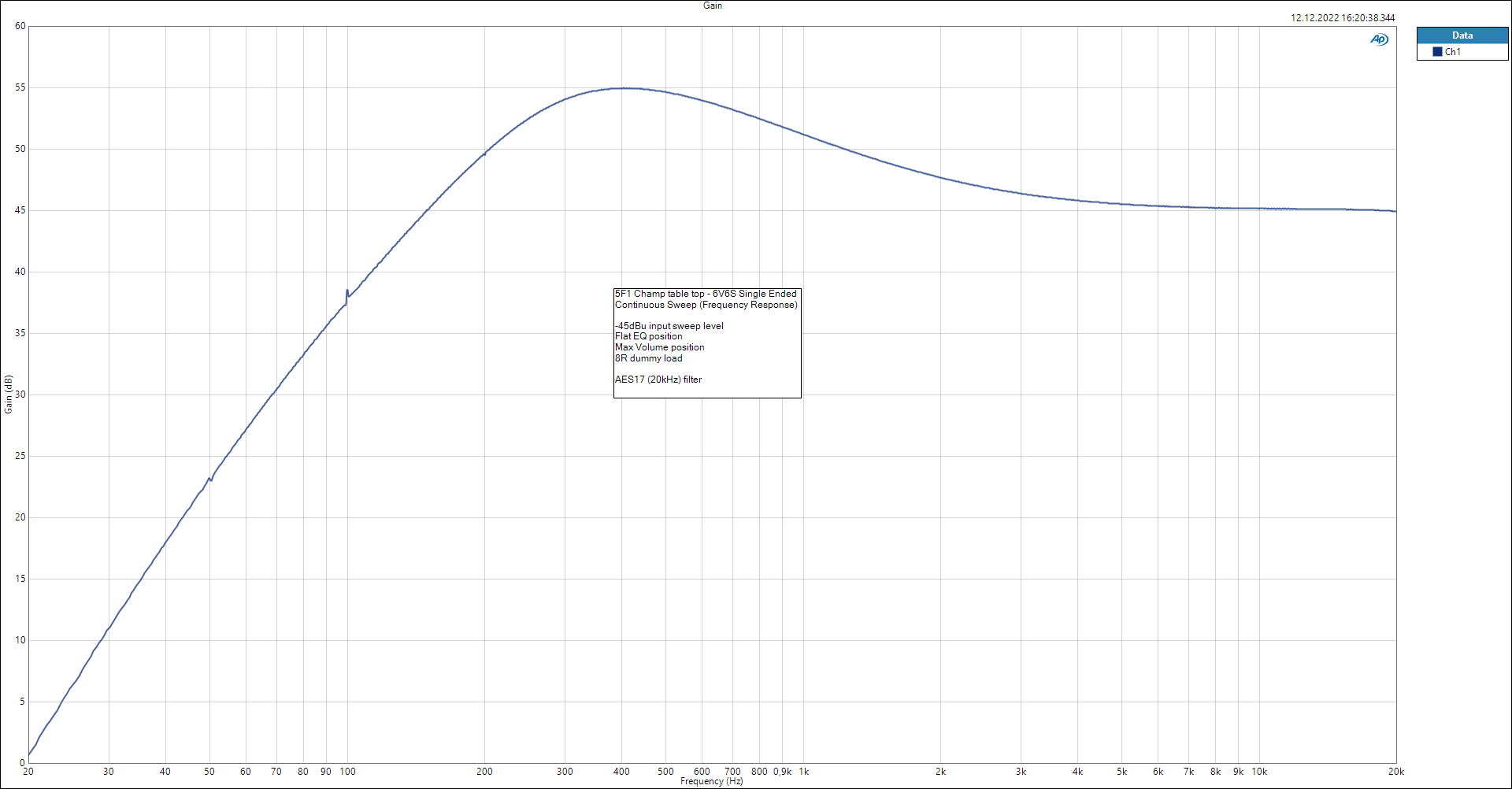
Frequency Response Gain
The frequency response shows how the amplifier shapes the guitar band before any subjective judgement is made. In a Champ-style circuit, the speaker and cabinet will later impose an even stronger voice, but testing into a dummy load reveals what the amplifier itself is doing.
Stepped Frequency Sweep
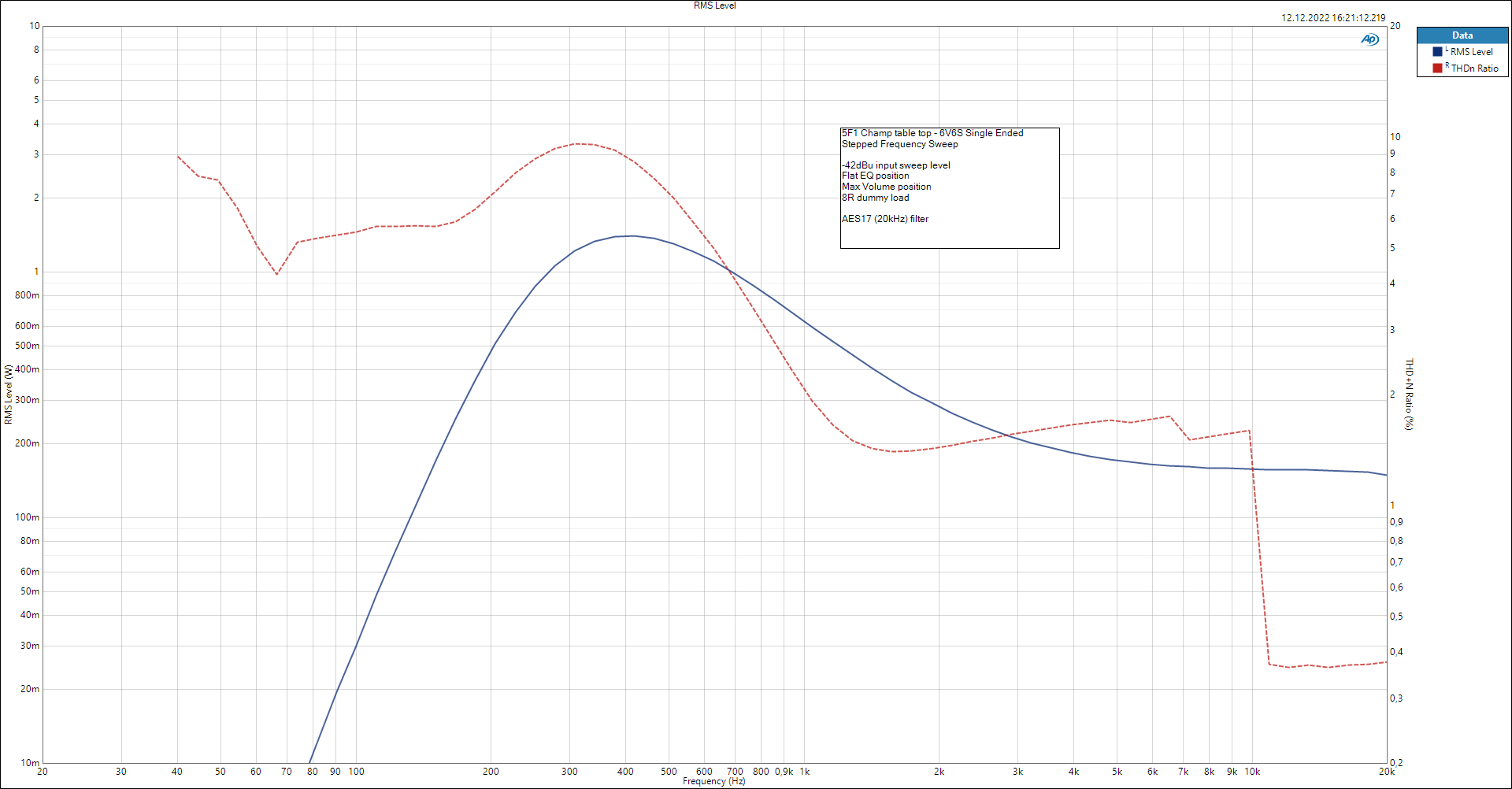
Stepped Frequency Sweep RMS Level
A stepped sweep is useful because it lets the analyzer settle at each frequency and measure the RMS level with greater stability. This can reveal low-frequency roll-off from coupling capacitors, transformer limitations, and high-frequency shaping from grid-stoppers, Miller capacitance, tone filters, and layout parasitics.
Stepped Level Sweep
RMS Level
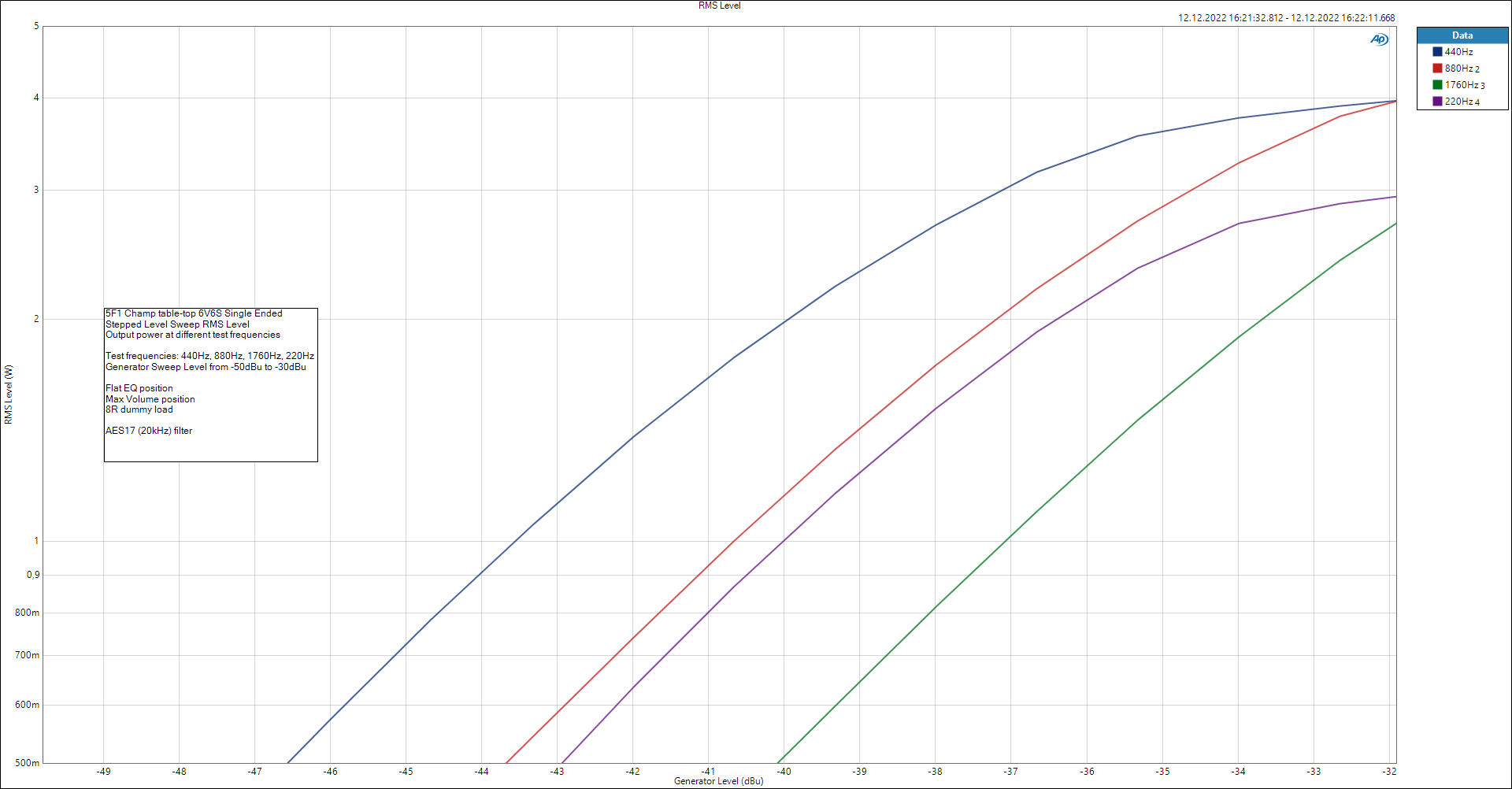
Stepped Level Sweep RMS Level
The level sweep shows how the output grows as the input increases. In a perfectly linear amplifier this would be a straight relationship. In a guitar amp, the interesting part is where the curve begins to bend.
THD+N vs. Measured Level
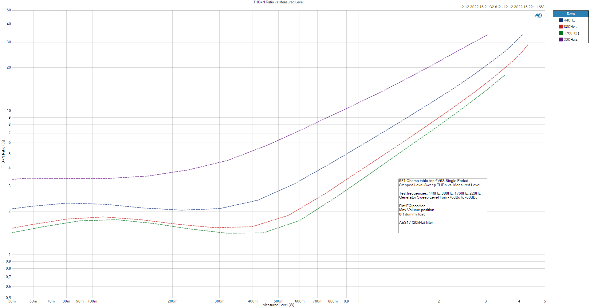
Stepped Level Sweep THD+N vs. Measured Level
THD+N rises as the amplifier leaves the clean region. In a single-ended tube amplifier this rise is not necessarily unpleasant. The distribution of harmonics matters at least as much as the total percentage.
FFT
FFT @ 440 Hz
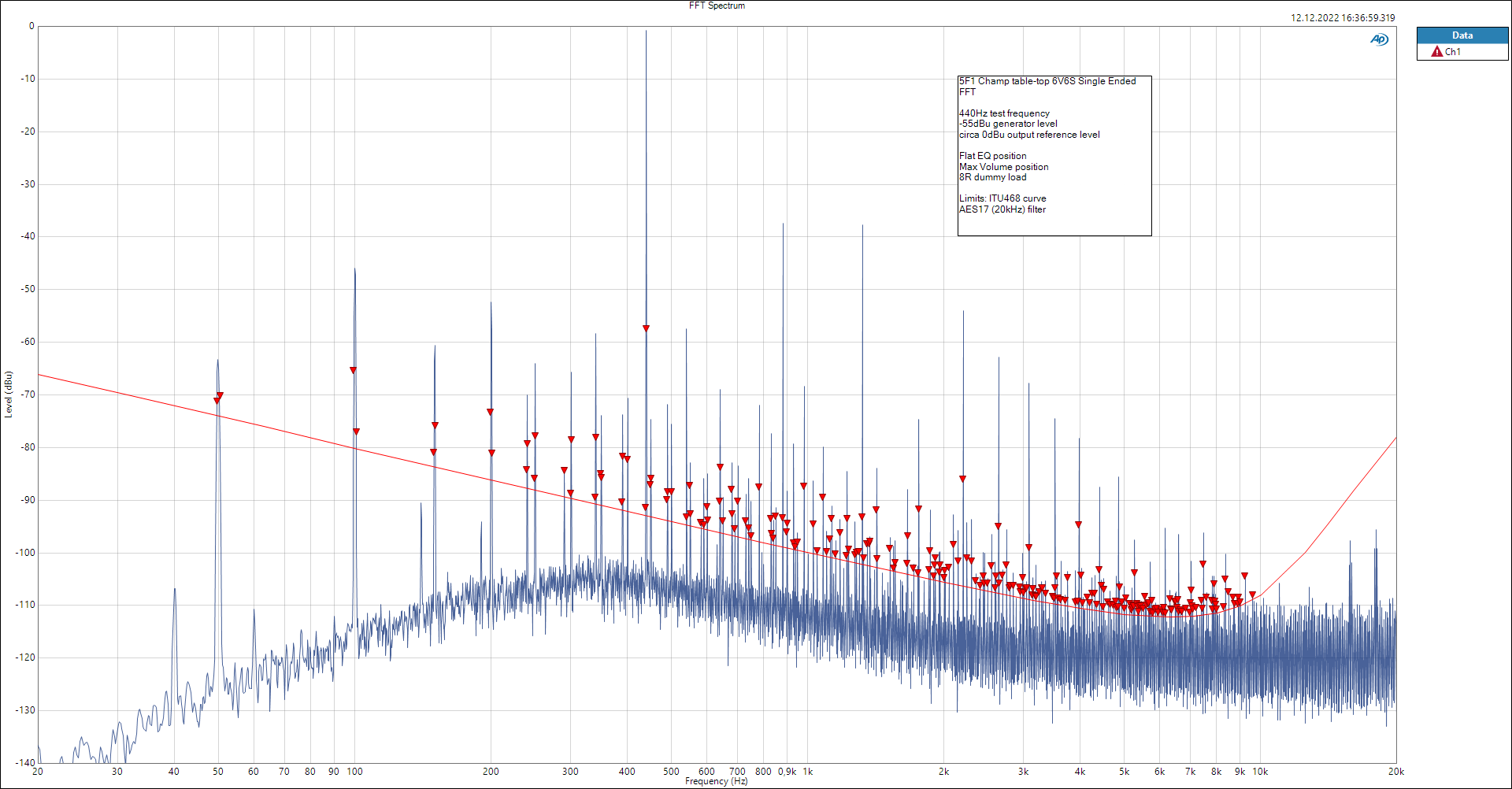
FFT @ 440Hz
A 440 Hz FFT is musically meaningful because it sits close to the pitch reference A4. It gives a clear view of harmonic content in a range that relates directly to notes played on the guitar.
FFT @ 1 kHz
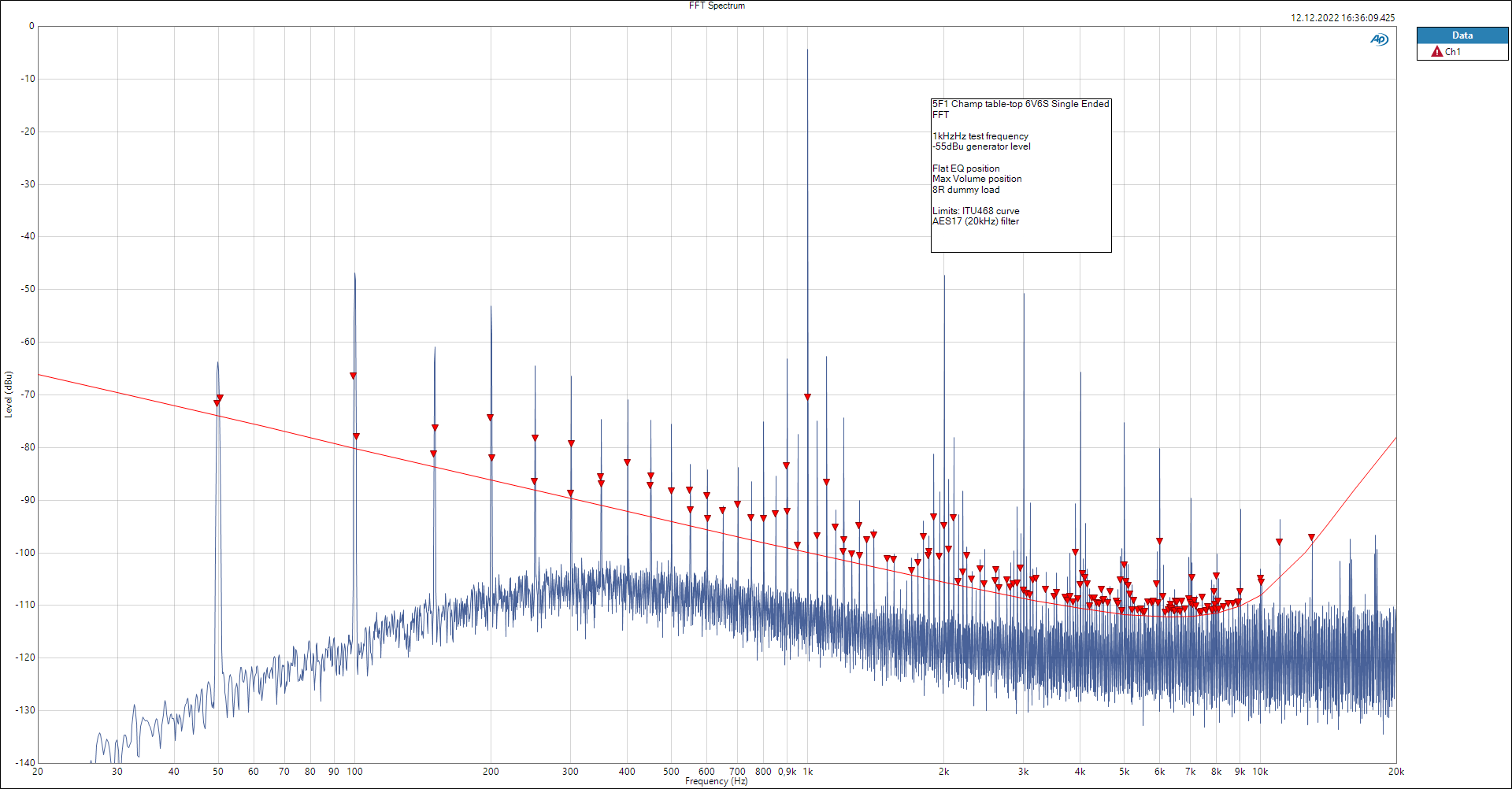
FFT @ 1kHz
A 1 kHz FFT is a common engineering reference point. It is useful for comparison because many amplifier specifications and distortion measurements are normalized around 1 kHz.
FFT Noise Floor
The noise floor matters more in the workshop than one might expect. Hum at 50 Hz and 100 Hz can point toward heater wiring, grounding, rectifier ripple, transformer placement, or insufficient filtering. Broadband hiss can point toward high-value resistors, noisy tubes, excessive gain, or layout issues around the first preamp stage.
Fender Champ-Amp 5F1 1957
The Fender Champ was introduced in the late 1940s and remained one of Fender’s simplest tube amplifiers for decades. I once had the chance to put my hands on an authentic late-1950s Fender Champ-Amp, similar to the one shown in the gallery below, and I was immediately fascinated by its simple construction and characteristic sound.
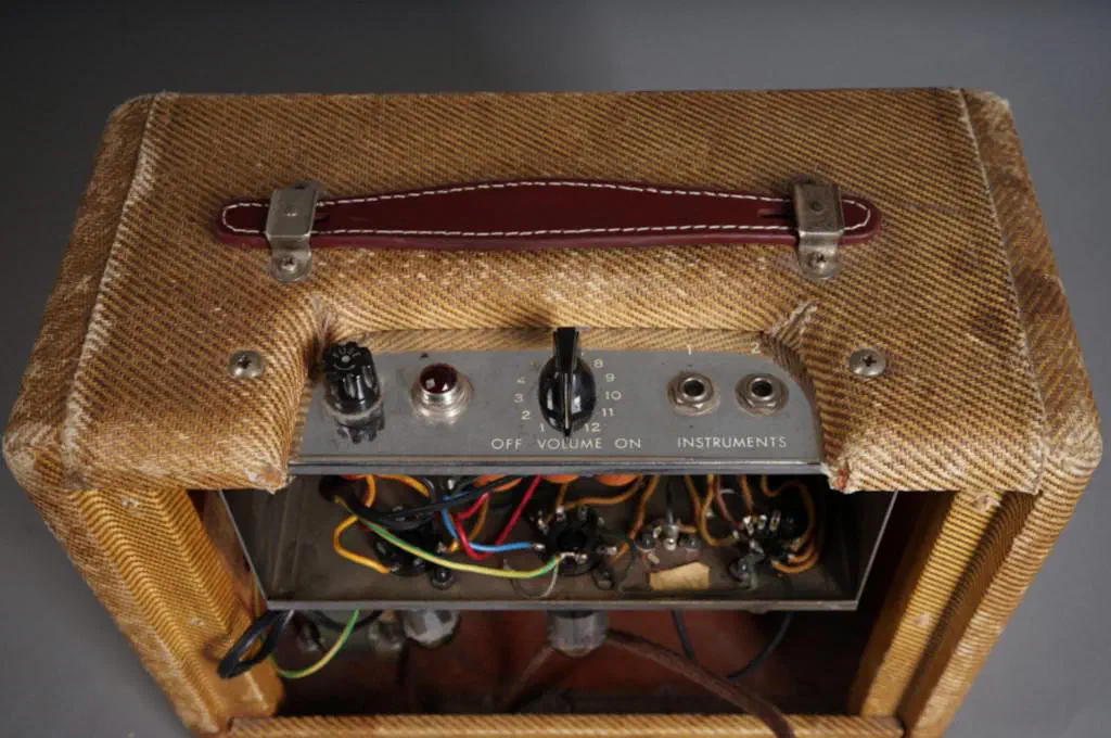
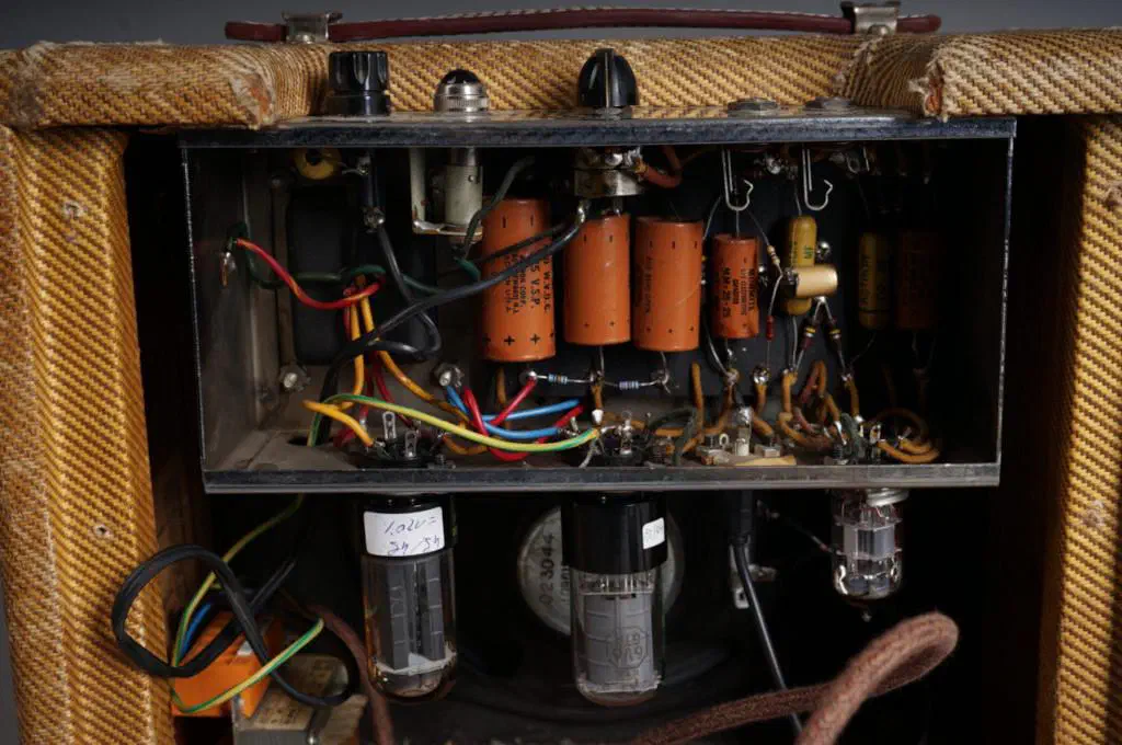
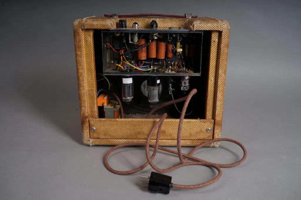
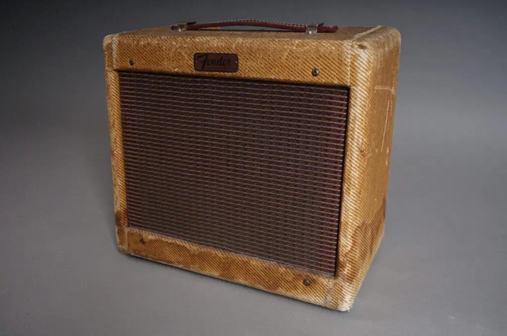
Here I collected some information about that original series.
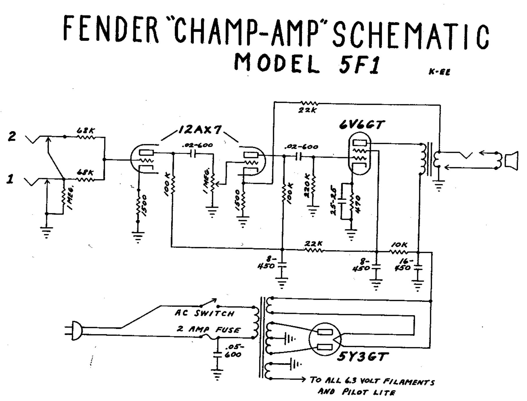
Fender Champ-Amp 5F1 original schematic
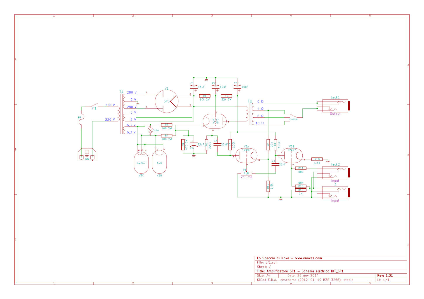
Fender Champ-Amp 5F1 original assembly layout
The power stage is single-ended class A and was originally equipped with a 6V6GT tube. With around five watts of output power and no tone-control circuit, the Champ became a perfect recording-studio tool: small enough to push hard, loud enough to feel alive, and simple enough to sit naturally in a mix.
Input Stage
The 5F1 provides two input jacks, usually described as high and low sensitivity.
The high input presents a high impedance to the guitar, normally referenced by a 1 MΩ resistor. The two 68 kΩ resistors act effectively in parallel as the grid-stopper path, giving roughly 34 kΩ before the first 12AX7 grid. This helps tame radio-frequency interference and prevents unwanted oscillation above the audio range.
The low input uses the two 68 kΩ resistors as a voltage divider, reducing the signal by about 6 dB before it reaches the first triode. It also presents a lower input impedance to the pickup, which can subtly reduce brightness. This is useful with hot pickups, humbuckers, or guitars that otherwise overdrive the first stage too quickly.
6V6GT, 6V6GTA and Modern 6V6S Tubes
The original 6V6 is a beam power tube introduced in 1939 as a smaller relative of the 6L6 family. It was produced in several forms, including glass and metal-envelope versions. In a Champ-style amplifier, the 6V6 is asked to do everything by itself: it conducts through the output transformer all the time and swings the complete output waveform alone.
Modern builders often use current-production 6V6 variants, including ruggedized types such as the JJ 6V6S. These can tolerate practical DIY conditions well, but the actual operating point still depends on the power transformer, rectifier, cathode resistor, screen voltage, and output transformer primary impedance. A Champ may look simple, but it still deserves proper voltage checks and dissipation calculations.
| Introduction date | 10 July 1939 |
|---|---|
| Base | Octal (Int.Octal, IO) K8A, USA 1935 |
| Heater / filament | 6.3 V, 450 mA |
| Heater warm-up time, average | about 11 s |
| Heater-cathode voltage, peak | ±200 V |
| Heater-cathode voltage, average | ±100 V |
| Grid No. 1 to plate capacitance | about 0.7 pF |
| Grid No. 1 to cathode, heater, grid No. 2 and grid No. 3 | about 9 pF |
| Plate to cathode, heater, grid No. 2 and grid No. 3 | about 7.5 pF |
6V6 in Class-A Single-Ended Amplifier Configuration
| Maximum ratings | |
|---|---|
| Plate voltage | 350 V |
| Grid No. 2 / screen-grid voltage | 315 V |
| Plate dissipation | 14 W |
| Grid No. 2 input | 2.2 W |
| Typical operation | |
|---|---|
| Plate voltage | 250 V |
| Grid No. 2 voltage | 250 V |
| Grid No. 1 / control-grid voltage | -12.5 V |
| Peak AF grid No. 1 voltage | 12.5 V |
| Zero-signal plate current | 45 mA |
| Maximum-signal plate current | 47 mA |
| Zero-signal grid No. 2 current | 7 mA |
| Plate resistance, approximate | 50 kΩ |
| Transconductance | 4100 µmho |
| Load resistance | 5 kΩ |
| Total harmonic distortion | 8% |
| Maximum-signal power output | 4.5 W |
| Characteristics in triode connection | |
|---|---|
| Plate voltage | 250 V |
| Grid No. 1 / control-grid voltage | -12.5 V |
| Amplification factor | 9.8 |
| Plate resistance, approximate | 1960 Ω |
| Transconductance | 5000 µmho |
| Plate current | 49.5 mA |
| Grid No. 1 voltage, approximate, for plate current of 0.5 mA | -36 V |
Grid No. 2 connected to plate.
Here are the diagrams from the 6V6S datasheet, which are more useful for practical modern builds unless one has genuine vintage tubes available.
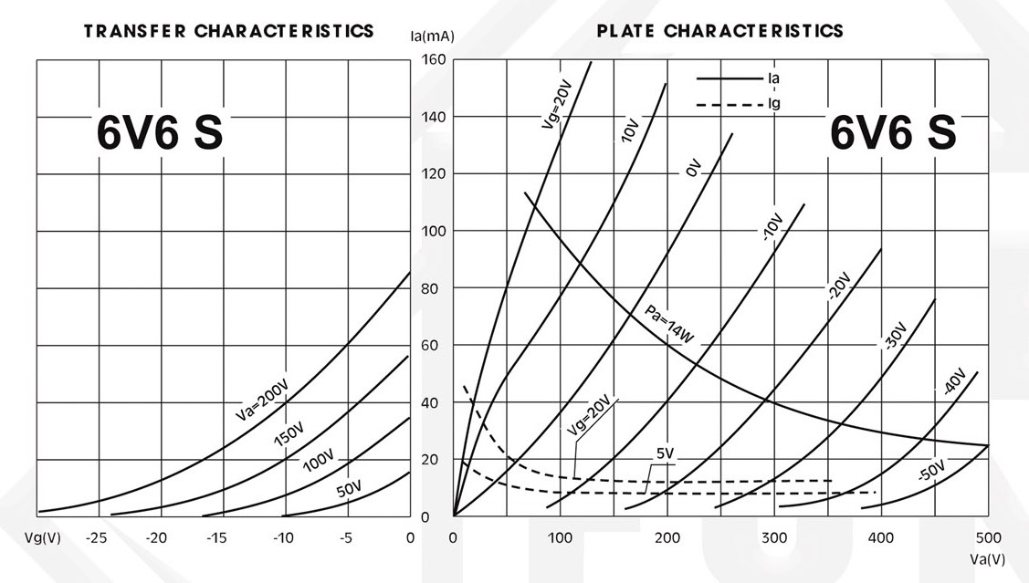
6V6S Curves
Equivalents:
6V6GT = 6П6С = VT-107A = CV511 = GT6V6 = 6V6GT/G = 6AY5 = 6V6_DDR
What These Builds Taught Me
The JCM800 and the 5F1 are both simple on paper, but they teach different lessons.
The Marshall teaches that high-gain amplifiers are mechanical-electrical systems. The schematic alone is not enough. Layout, grounding, transformer orientation, shielding, and wire routing determine whether the amp is quiet, stable, and reliable.
The Champ teaches that simplicity exposes everything. With so few components, each value change is audible. The rectifier, speaker, output transformer, cabinet, and guitar pickup all become part of the instrument.
Together they form a perfect DIY education: one loud, complex enough to be dangerous and demanding; the other small, honest, and endlessly modifiable.
Further Reading
- How the Marshall Plexi, 2204 and JCM800 Amplifiers Work — Rob Robinette
- Marshall JCM800 2204 Power Amp — AmpBooks
- How Fender Normal/Bright/Hi/Low Input Jacks Work — Rob Robinette
- Gibson GA-5 vs Fender 5F1: Circuit Analysis — Tropical Fish Vintage
- VOX Lil’ Night Train specifications — VOX Amps
- VOX Night Train NT15H review — Premier Guitar