Building a Digital Scooter Speedometer in the Late 1990s
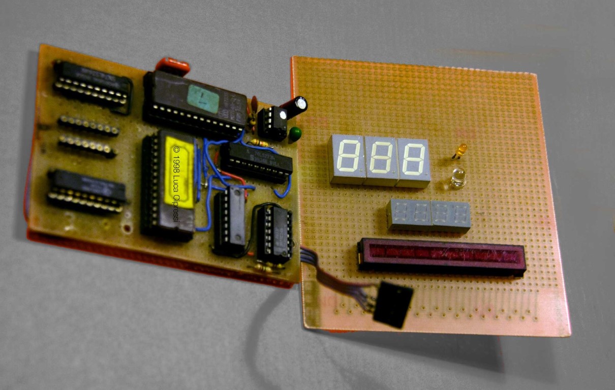
A relic from my late high-school years in the late 1990s. Remarkably, the electronics are still technically functional today, although the original display board disappeared long ago. One day I may attempt a complete restoration. The display shown in the photographs is only a mock-up reproducing what the original dashboard looked like.
“Car’s got a lot of pickup.” — The Blues Brothers (1980)
Like many teenagers of the era, I spent countless hours riding and tinkering with my 50 cc scooter. Mine was no exception: over time it became so heavily modified that it was probably no longer road-legal.
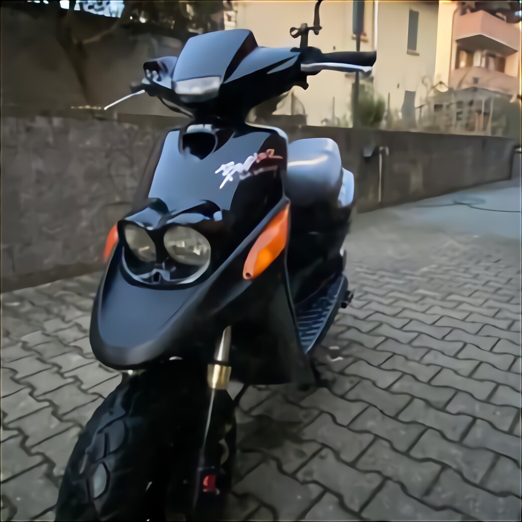
Back then, scooter tuning was almost a rite of passage. Exhaust systems, variators, carburettors, air filters and cylinders were routinely swapped in pursuit of a few extra kilometres per hour.
“It’s got a cop motor, a 440 cubic inch plant, it’s got cop tires, cop suspensions, cop shocks…” — The Blues Brothers (1980)
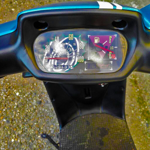
The original instrument cluster looked like this:
In addition to the stock 50 cc engine, my scooter eventually featured a 70 cc cylinder kit, a performance exhaust, a modified continuously variable transmission (CVT), an upgraded clutch, a sport crankshaft and a larger carburettor. But perhaps the most unusual modification was this entirely home-built digital speedometer.
MAIN BOARD
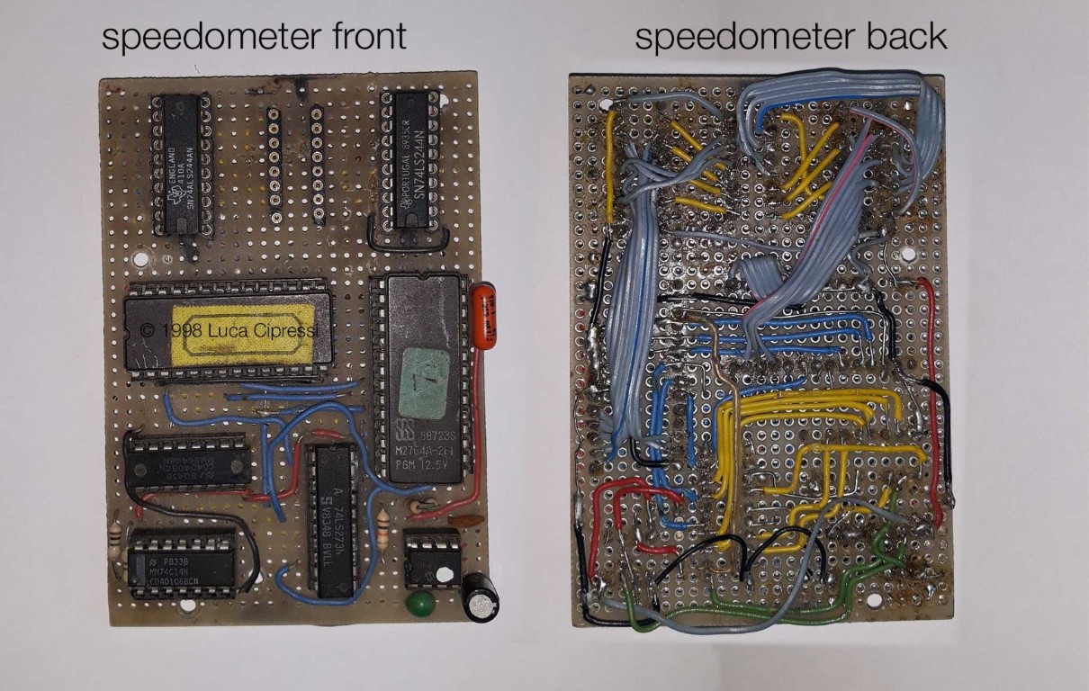
The main board was assembled entirely by hand. At the time I had neither a proper PCB fabrication service nor professional tools. Many of the connections were made using pieces of salvaged wire soldered point-to-point on perfboard.
The soldering iron itself deserves a special mention: it was a very inexpensive model connected directly to 230 VAC, with no temperature regulation whatsoever. It would quickly overheat, so the only way to control its temperature was simply to unplug it from the mains every now and then. Unsurprisingly, some solder joints look rather rough by today’s standards.
Schematic (Main Board)
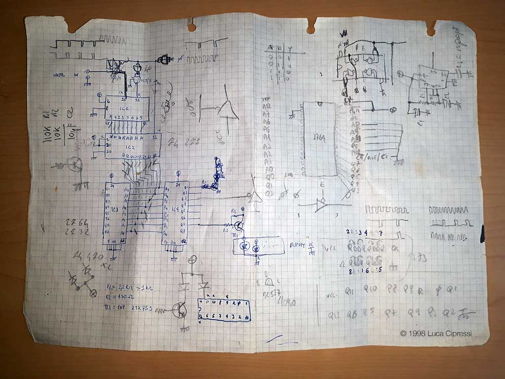
This is one of the few surviving original documents related to the project. During lessons I would often fill entire notebooks with sketches, calculations and circuit ideas instead of paying full attention in class. Looking at these pages today feels like opening a time capsule.
I did choose to rely on discrete logic circuits instead of a MCU like a PIC16 series. They were expensive and definitely not easy to source for a teenager student. Additionally I was really into logic ports, multiplexers and bare-metal 6502 programming at the time, so it seemed to me the best approach and it worked flawlessly!
Calculations (EPROM LUT)
The speed measurement principle was based on sensing the rotation of the front brake disc, which conveniently featured six equally spaced holes:


Knowing the wheel circumference, calculating the vehicle speed could have been performed by a microcontroller using floating-point arithmetic. However, at the time affordable microcontrollers with sufficient memory and development tools were not readily available to me.
Instead, I devised a rather unconventional solution using surplus EPROM memories.
The six pulses generated by the brake disc sensor were counted by a CD4040 binary counter during a one-second gate interval generated by an NE555 configured as a monostable. The resulting 12-bit count directly addressed two M2764 EPROMs.
Before programming the memories, I calculated all possible speed values in advance. Each EPROM therefore contained a lookup table: one stored the units digit and the other the tenths digit of the speed. The outputs were already encoded for seven-segment displays, requiring only a buffer stage before driving the LEDs.
In modern terminology, this was essentially a hardware lookup-table implementation.
Reaching speeds above 100 km/h was unlikely, but with all the modifications — and perhaps a favourable tailwind while descending a hill — the scooter could occasionally exceed that threshold. To minimise component count, the most significant bit of the EPROM outputs was also reused to drive segments b and c of the hundreds digit.
Assembling the board proved to be one of the most challenging parts of the project. Working with salvaged components, mismatched wire gauges and rudimentary tools required considerable patience. In hindsight, the fact that the circuit still operates after almost thirty years is probably the most surprising achievement of all.
Parts List (Main Board)
| Part Number | Description |
|---|---|
| NE555 | Monostable generating a 1-second gate pulse |
| 74HC14 | Schmitt-trigger inverter |
| CD4040 | 12-bit binary counter |
| 74LS273 | Octal D-type flip-flop register |
| M2764A (×2) | 64-kbit EPROM used as lookup tables |
| 74LS244 | Octal buffer used to drive the display segments |
DISPLAY BOARD
The display assembly shown here is a pretty much faithful reconstruction. The original unit was designed to fit inside the scooter’s cockpit in place of the factory analogue cluster. The initial design was rather ambitious and included provisions for fuel level indication, trip and total mileage counters, turn indicators and high-beam warning lights.
The original fuel sensor was a current-driven milliammeter gauge, so a simple current/voltage conversion stage was implemented on it to drive an LED bar. I believe I did implement a transconductance amplifier and some comparator stages to light up the corresponding LEDs.
Other indicators were directly connected to respective LEDs via a current limiting resistor.